Sokkia iM-50 Series Operator'S Manual Download Page 177

172

31. OUTPUTTING JOB DATA

7. Select the output format and press 

{ENT}

When "GTS (Obs)" or "SSS (Obs)" is selected, select the 
output format of distance data.
• Selecting "Obs data" outputs the slope distance. Selecting 

"Reduced data" outputs the horizontal distance data 
converted from the slope distance. (When the SSS format 
is selected, the height difference is also output.) 

• When the instrument station data is not recorded during the 

measurement, selecting "Reduced data" may cause output of 
an unintended measurement result.

8. Press 

{ENT}

 to start outputting data in the current JOB. 

After output is completed, the screen returns to the list of 
JOBs, where you can output data in other JOBs.

• Press 

{ESC}

 to stop data output in progress.

PROCEDURE Code output to a host computer

• Only the codes for communication formats compatible with "T type" can be output.
• When outputting the code, it is necessary to select "T type" in the communication setting.

"33.1 Observation Conditions - Angle/Tilt"  Communication Setup

1. Connect the iM and a host computer in advance.

2. Select "Code" in the Data mode.

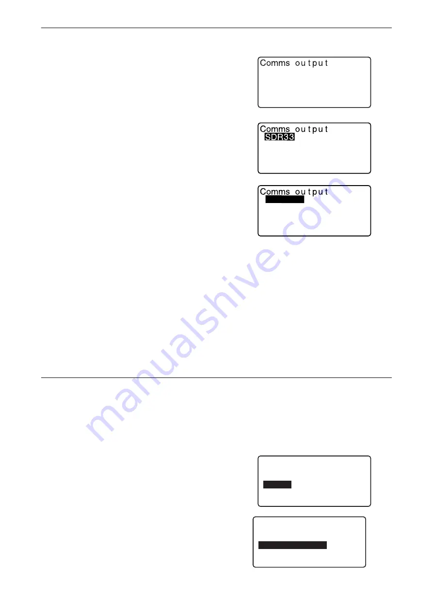
3. Select "Comms output" and press 

{ENT}

. Code output 

begins. After code output is completed, the screen returns 
to the Code menu.

SDR2X

When S type is selected

When T type is selected

GTS(Obs)
GTS(Coord)
SSS(Obs)
SSS(Coord)

Obs data

Reduced data

D a t a
  J O B
  K n o w n   d a t a

  C o d e

C o d e
  K e y   i n   c o d e
  C o m m s   i n p u t

  C o m m s   o u t p u t

  D l e t i o n
  C o d e   v i e w

Summary of Contents for iM-50 Series

Page 1: ...SURVEYING INSTRUMENTS Class 3R Laser Product OPERATOR S MANUAL 1025821 02 A iM 50 series intelligence Measurement Station ...

Page 2: ...mentary explanation Indicates an explanation for a particular term or operation MEAS etc Indicates Operation icons on the display and window dialog buttons ESC etc Indicates keys on the operation panel Screen title etc Indicates screen titles Notes regarding manual style Except where stated iM means iM 50 series in this manual Except where stated instrument with display on both sides is used for i...

Page 3: ...n Two Points Horizontal Angle 0 34 11 2 Setting the Horizontal Angle to a Required Value Horizontal Angle Hold 35 11 3 Horizontal Angle Repetition 36 11 4 Angle Measurement and Outputting the Data 37 12 DISTANCE MEASUREMENT 38 12 1 Returned Signal Checking 38 12 2 Distance and Angle Measurement 39 12 3 Recalling the Measured Data 40 12 4 Distance Measurement and Outputting the Data 40 12 5 Coordin...

Page 4: ...tion 121 25 4 Spiral Curve 122 25 5 Parabola 127 25 6 3 Point Calculation 130 25 7 Intersection Angle Azimuth Angle Calculation 132 25 8 Route Calculation 134 26 CROSS SECTION SURVEY 145 27 Point to Line MEASUREMENT 149 28 RECORDING DATA TOPO MENU 152 28 1 Recording Instrument Station Data 152 28 2 Recording Backsight Point 154 28 3 Recording Angle Measurement Data 155 28 4 Recording Distance Meas...

Page 5: ...s Power 186 33 7 Instrument Conditions Unit 187 33 8 Instrument Conditions Instrument 187 33 9 Instrument Conditions Password 188 33 10Instrument Conditions Date and Time 189 33 11Allocating Key Functions 190 33 12Restoring Default Settings 193 34 WARNING AND ERROR MESSAGES 194 35 CHECKS AND ADJUSTMENTS 198 35 1 Circular Level 198 35 2 Tilt Sensor 198 35 3 Reticle 201 35 4 Collimation 201 35 5 Opt...

Page 6: ...in areas where there is inadequate ventilation or near combustible materials An explosion could occur Do not perform disassembly or rebuilding Fire electric shock burns or hazardous radiation exposure could result Never look at the sun through the telescope Loss of eyesight could result Do not look at reflected sunlight from a prism or other reflecting object through the telescope Loss of eyesight...

Page 7: ...ers into fire An explosion could occur resulting in injury To prevent shorting of the battery in storage apply insulating tape or equivalent to the terminals Otherwise shorting could occur resulting in fire or burns Do not use the battery or the battery charger if its terminals are wet Resultant poor contact or shorting could lead to fire or burns Do not connect or disconnect power supply plugs wi...

Page 8: ... with a cardiac pacemaker Otherwise the pacemaker may be adversely affected by the electromagnetic waves produced and cease to operate as normal Do not use onboard aircraft The aircraft instrumentation may malfunction as a result Do not use within the vicinity of automatic doors fire alarms and other devices with automatic controls as the electromagnetic waves produced may adversely affect operati...

Page 9: ...he handle attached always make sure that the handle is securely fixed to the instrument body with the handle locks Precautions concerning water and dust resistance The instrument conforms to IP66 specifications for waterproofing and dust resistance when battery cover connector cap and the external interface hatch are closed Be sure to correctly attach the connector caps to protect the instrument f...

Page 10: ...e power off before removing the battery When placing the iM in its case first remove its battery and place it in the case in accordance with the layout plan Make sure that the instrument and the protective lining of the carrying case are dry before closing the case The case is hermetically sealed and if moisture is trapped inside the instrument could rust Consult your local dealer before using the...

Page 11: ...h telecommunications regulations of the country where the instrument is being used Even exporting the wireless communication module may require conformity with the regulations Contact your local dealer in advance Exceptions from responsibility The manufacturer or its representatives assumes no responsibility for any damage or loss of profits change of data loss of data loss of profits an interrupt...

Page 12: ... use of this laser product Never intentionally point the laser beam at another person The laser beam is injurious to the eyes and skin If an eye injury is caused by exposure to the laser beam seek immediate medical attention from a licensed ophthalmologist Do not look directly into the laser beam source Doing so could cause permanent eye damage Do not stare at the laser beam Doing so could cause p...

Page 13: ... could cause serious injury Only those who have been received training as per the following items shall use this product Read this manual for usage procedures for this product Hazardous protection procedures read this chapter Requisite protective gear read this chapter Accident reporting procedures stipulate procedures beforehand for transporting the injured and contacting physicians in case there...

Page 14: ...laser plummet 12 Display unit 13 Objective lens Includes Laser pointer function 14 Handle locking screw 15 Tubular compass slot 16 Vertical clamp 17 Vertical fine motion screw 18 External interface hatch USB port Reset button 19 Horizontal fine motion screw 20 Horizontal clamp 21 Tribrach clamp 22 Telescope eyepiece screw 23 Telescope focussing ring 24 Sighting collimator Gun sight on iM 55 in Fac...

Page 15: ...ight is mounted on Face 2 position of the iM 55 Align the telescope to the direction of the target in such a way that the gun sight is positioned with the target as shown below Note that you see the target at a distance from the gun sight Horizontal direction a position where you can see both the target and back sight at the center of the front sight s slit Vertical direction a position where you ...

Page 16: ...m the tribrach 1 Turn the tribrach clamp counterclockwise to loosen 2 Lift the instrument to detach Attaching the instrument to the tribrach 1 Align 1 and 2 and lower the instrument onto the tribrach 2 Turn the tribrach clamp clockwise to tighten 1 2 ...

Page 17: ...S O Arc Dist Coord Note View Deletion TILT H SET EDM MENU OBS PC 0 0 ppm SD ZA HA R 89 0 59 00 50 00 SHV MEAS 0SET COORD iM 52 S N XX123456 Date Jan 01 2017 Time 12 00 00 rec 49999 CNFG OBS USB DATA iM 52 S N XX123456 Internal Pt 50000 Bluetooth rec 49999 CNFG OBS USB DATA iM 52 S N XX123456 Ver X XXXX_XX X XXX Job JOB1 rec 49999 CNFG OBS USB DATA TOPO JOB1 Occupy BS data Angle data Dist data Coor...

Page 18: ...the iM within proximity to the above devices may result in interference causing communication failure or reduction of transmission speed Although a radio station license is not required for this instrument bear in mind the following points when using Bluetooth technology for communication Regarding portable premises radio equipment and portable specified low power radio equipment Before starting t...

Page 19: ...glass and plastic containing metal frames plates foil and other heat shielding elements as well as coatings containing metallic powders may adversely affect Bluetooth communication and concrete reinforced concrete and metal will render it impossible Use a vinyl or plastic cover to protect the instrument from rain and moisture Metallic materials should not be used The direction of the Bluetooth ant...

Page 20: ... Conditions Dist Switching the Laser pointer light ON OFF Switching function 33 7 Instrument Conditions Instrument After turning ON the laser pointer the laser beam is emitted for 5 minutes and then automatically switches OFF But in the Status screen and when target symbol ex is not displayed in the OBS mode the laser beam is not automatically turned off 5 1 Basic Key Operation Switches the reticl...

Page 21: ...1 to F4 Select the function matching the softkeys FUNC Toggle between OBS mode screen pages when more than 4 softkeys are allocated SHIFT Switch between numeric and alphabetic characters 0 to 9 During numeric input input number of the key During alphabetic input input the characters displayed above the key in the order they are listed Input a decimal point plus or minus sign during numeric input D...

Page 22: ... and you can set the next item Switching modes 4 2 Mode Structure Others Move the cursor up down Move the cursor selection item left right or select other option ENT Accepts the option From OBS mode Observation Mode to Starkey Mode CNFG From Status mode to Config Mode Configuration Mode OBS From Status mode to OBS mode Observation Mode USB From Status mode to USB Mode DATA From Status mode to Data...

Page 23: ...c 49999 CNFG OBS USB DATA Date Time iM 52 S N XX123456 Internal Pt 50000 Bluetooth rec 49999 CNFG OBS USB DATA Functions on your instrument SHV MEAS 0SET COORD OBS SD ZA HA R Distance 1 Vertical angle 2 Horizontal angle 3 Bluetooth communication status 8 Laser pointer function ON 7 Prism constant value Atmospheric correction factor Remaining battery power 4 Tilt angle compensation 6 Page number Ta...

Page 24: ...T to switch the selected target This key function can be used only on the screens on which the target symbol is displayed prism reflective sheet reflectorless 6 Tilt angle compensation When this symbol is displayed the vertical and horizontal angles are automatically compensated for small tilt errors using 2 axis tilt sensor Tilt compensation setting 33 1 Observation Conditions Angle Tilt 7 Laser ...

Page 25: ...Starkey mode you can change the setting commonly used for measuring The following operations and settings can be made in the Starkey mode 1 Turning ON OFF tilt angle correction 2 Adjusting the display unit s contrast Steps 0 15 3 Adjusting reticle illmination level Steps 0 5 4 Switching the target type 5 Turning ON OFF laser plummet for the instrument with the laser centering function The Starkey ...

Page 26: ...anges For long term storage the battery should be charged at least once every six months Batteries generate power using a chemical reaction and as a result have a limited lifetime Even when in storage and not used for long periods battery capacity deteriorates with the passage of time This may result in the operating time of the battery shortening despite having been charged correctly In this even...

Page 27: ...the battery turn OFF the power to the instrument Do not open the battery cover while the power is on When installing removing the battery make sure that moisture or dust particles do not come in contact with the inside of the instrument Waterproofing property for this instrument is not secured unless the battery cover and external interface hatch are closed and the connector caps are correctly att...

Page 28: ...are firmly fixed in the ground 2 Place the instrument on the tripod head Supporting it with one hand tighten the centering screw on the bottom of the unit to make sure it is secured to the tripod 3 Looking through the optical plummet eyepiece turn the optical plummet eyepiece to focus on the reticle Turn the optical plummet focussing ring to focus on the survey point 4 Adjust the levelling foot sc...

Page 29: ...itted from the bottom of the instrument Use in the second page to adjust the brightness of the laser 4 Using levelling foot screws adjust the position of the instrument on the tripod until the laser beam is aligned with the center of the survey point 5 Press L OFF to turn the laser plummet off Alternatively press ESC to return to the previous screen The laser plummet will switch off automatically ...

Page 30: ...e instrument tilted the circular level is displayed on the screen 4 Using levelling foot screws center in the circular level First turn the instrument until the telescope is parallel to a line between levelling foot screws A and B Next set the tilt angle to 0 using foot screws A and B for the X direction and levelling screw C for the Y direction When the bubble is in the center proceed to step 5 5...

Page 31: ...trument and press OK Manually indexing the vertical circle by Face 1 2 measurements 40 EXPLANATIONS If Out of range or the Tilt screen is displayed level the instrument again Tilt crn in Obs condition should be set to No if the display is unsteady due to vibration or strong wind 33 1 Observation Conditions Angle Tilt When Resume in Instr config is set to On the screen previous to power off is disp...

Page 32: ...period can be set in Power off in Instr config 33 1 Observation Conditions Angle Tilt In some cases it may take longer until Power OFF Do not remove the battery until the display turns off Doing so will cause data stored in the iM to be lost Reset button If you are experiencing problems with the software depress the reset button to reboot the program forcibly Use a provided hexagonal wrench 1 3 mm...

Page 33: ...of Bluetooth devices requires one device to be set as the Master and the other as the Slave iM is always Slave and the paired data collector will be the Master when performing measurements and recording the data between them When restoring set items to initial settings reconfigure the Bluetooth communication settings PROCEDURE Setting for Bluetooth communication 1 Select Comms setup in Config mode...

Page 34: ...et as Master 8 Press ENT to finish settings Move on to the Bluetooth communication 9 2 Communication between the iM and Companion Device Bluetooth device address This is a number unique to one particular Bluetooth device used to identify devices during communication This number consists of 12 characters numbers 0 to 9 and letters from A to F Some devices may be referred to by their Bluetooth devic...

Page 35: ...etc is turned on and the relevant Bluetooth settings are complete All communication settings will be changed to factory settings when a cold boot is performed Comms setup will need to be performed again 9 1 Wireless Communication using Bluetooth Technology When Mode is set to Bluetooth in Comms setup in Config mode is displayed in OBS mode Softkeys in OBS mode Audio tones While connecting disconne...

Page 36: ...ection by the data collector RS232C communication is possible connecting instrument and a data collector with the cable PROCEDURE Basic cable settings 1 Power OFF the instrument and connect the instrument and a data collector with a interface cable Cables 38 ACCESSORIES Insert the interface cable to the serial external power source connector tightly and then turn it 2 Select Comms setup in Config ...

Page 37: ...ng for RS232C Items set and options Factory setting 1 Baud rate 1200 2400 4800 9600 19200 38400bps 2 Data bits 7 8 bits 3 Parity Not set Odd Even 4 Stop bit 1 2 bits 7 Press ENT to finish settings Comms setup Comms mode Comms type RS232C Bluetooth Baud rate Data bits Parity Stop bit 9600bps 8bit None 1bit ...

Page 38: ... vertical and horizontal clamps then use the sighting collimator to bring the target into the field of view Tighten both clamps 3 Focus on the target Turn the telescope focussing ring to focus on the target Turn the vertical and horizontal fine motion screws to align the target with the reticle The last adjustment of each fine motion screw should be in the clockwise direction 4 Readjust the focus ...

Page 39: ... 10 TARGET SIGHTING AND MEASUREMENT 2 In the first page of the OBS mode screen press 0SET 0SET will flash so press 0SET again The horizontal angle at the first target becomes 0 3 Sight the second target The displayed horizontal angle HA R is the included angle between two points 11 1 Measuring the Horizontal Angle between Two Points Horizontal Angle 0 OBS PC 0 0 ppm SD ZA HA R 89 0 59 00 50 00 MEA...

Page 40: ...nd target The horizontal angle from the second target to the value set as the horizontal angle is displayed Pressing HOLD performs the same function as above Press HOLD to set the displayed horizontal angle Then set the angle that is in hold status to the direction you require Allocating HOLD 33 11 Allocating Key Functions PROCEDURE Entering the coordinate 1 Press H SET on the second page of the O...

Page 41: ...er precision perform repetition measurement The maximum number of angle measurements that can be made is 10 PROCEDURE 1 Allocate REP to the Meas mode screen then press REP Repetition is displayed Allocating REP 33 12 Allocating Key Functions 2 Sighting the first target press OK 3 Sighting the second target press OK 4 Sighting the first target a second time press OK 11 3 Horizontal Angle Repetition...

Page 42: ...ESC The following explains angle measurement and the features used to output measurement data to a computer or peripheral equipment Bluetooth communication 9 CONNECTING TO EXTERNAL DEVICES Communication cables 38 ACCESSORIES Output format and command operations Communication manual PROCEDURE 1 Connect iM and host computer 2 Allocate the HVOUT T or HVOUT S softkey to the OBS mode screen 33 11 Alloc...

Page 43: ...ot be obtained if the objective lens is dirty Dust it off with the lens brush first to remove minute particles Then after providing a little condensation by breathing on the lens wipe it off with the silicon cloth During reflectorless measurement if an object obstructs the light beam used for measurement or an object is positioned with a high reflective factor metal or white surface behind the tar...

Page 44: ...isplayed persistently contact your local dealer If no key operations are performed for two minutes the display automatically returns to the OBS mode screen An angle can be measured at the same time as the distance PROCEDURE 1 Sight the target 2 In the first page of OBS mode press MEAS to start distance measurement When measurement starts EDM information distance mode prism constant correction valu...

Page 45: ...The distance measurement value vertical angle horizontal angle and the coordinates can be displayed Distance measurement values converted into the horizontal distance elevation difference and the slope distance can also be displayed PROCEDURE 1 Allocate the CALL softkey to the OBS mode screen 33 11 Allocating Key Functions 2 Press CALL The stored data that is most recently measured is displayed If...

Page 46: ...ting procedures 9 CONNECTING TO EXTERNAL DEVICES Communication cables 38 ACCESSORIES Output format and command operations Communication manual PROCEDURE 1 Connect iM and host computer 2 Allocate the NEZOUT T or NEZOUT S softkey to the OBS mode screen 33 11 Allocating Key Functions Pressing the softkey outputs data in the following format NEZOUT T GTS format NEZOUT S SET format 3 Sight the target p...

Page 47: ...d from the calculation Null is different from 0 PROCEDURE 1 Set the target directly under or directly over the object and measure the target height with a tape measure etc 2 After inputting the target height accurately sight the target Press MEAS in page 1 of OBS mode to carry out measurement The measured distance data SD vertical angle ZA and horizontal angle HA R are displayed Press STOP to stop...

Page 48: ...ge of the REM measurement to display the Z coordinate for the height from the ground to the target Pressing HT Z again returns to the height display 7 Press ESC to finish measurement and return to the OBS mode screen It is also possible to perform REM measurement by pressing REM when allocated to the OBS mode screen 33 11 Allocating Key Functions Inputting instrument and target height Press HT to ...

Page 49: ...lanation below is an example of when coordinate measurement is selected 13 1 Entering Instrument Station Data and Azimuth Angle Key input 13 1 Entering Instrument Station Data and Azimuth Angle Step 3 Reading the registered coordinate 13 1 Entering Instrument Station Data and Azimuth Angle PROCEDURE Reading in Registered Coordinate Data Calculating data by resection measurement 13 2 Setting Instru...

Page 50: ...Angle from Backsight Coordinates 5 Input azimuth angle and press OK to set the input values Coord is displayed again Press REC to record the following data Instrument station data RED Reduced data backsight station data and angle measurement data Press OK to set the input values and return to Coord Maximum point name size 14 alphanumeric Input range of instrument height 9999 999 to 9999 999 m Maxi...

Page 51: ...in the Coordinate Search JOB 2 Align the cursor with the required point name and press ENT The point name that was read and its coordinates are displayed Use to move from page to page P Use to select individual point Press FIRST to move to the first point name on the first page Press LAST to move to the last point name on the last page Press SRCH to move to the Coordinate Data Search Screen 13 1 1...

Page 52: ...nt name searches forward from the current point name PROCEDURE Coordinate Data Search Partial match 1 Press Search in the registered coordinate data list screen All coordinate data that includes characters and numbers entered in step 2 is displayed 2 Enter search criteria Enter the following items 1 Partial coordinate point name 2 Search condition partial match 3 Press OK to display data that matc...

Page 53: ...ement When measuring is completed the backsight distance check screen is displayed The difference between the calculated value and the measured height distance value is displayed After confirming press OK Press HT to set instrument and target height Press REC to store check data in the current JOB Press REC to record the following data Instrument station data backsight station data known point dat...

Page 54: ...N and E Always perform resection measurement in the sequence described in 13 2 2 Coordinate Resection Measurement and 13 2 4 Height Resection Measurement Input known coordinate data and calculated instrument station data can be recorded in the current JOB 29 SELECTING DELETING A JOB 13 2 1 Observation setting Perform observation setting prior to resection measurement 1 Select Occ Orien 2 Press RES...

Page 55: ...f coordinate resection Press σNEZ to display standard deviation which describes the measurement accuracy Press NEZ to return to the instrument station coordinate screen σZ can be displayed by pressing in the result screen in which is displayed Choices of the setting are as follows is the default setting RL observation Yes No Display σZ On Off Resection NEZ Elevation Setting Setting F1 F2 Obs Z No ...

Page 56: ...ance cannot be displayed 5 Press YES to use the measurement results of the first known point You can also input target height here 6 Input coordinates for the first known point and press NEXT to move to the second point When LOAD is pressed registered coordinates can be recalled and used 13 1 Entering Instrument Station Data and Azimuth Angle PROCEDURE Reading in Registered Coordinate Data Press E...

Page 57: ...ion again without the point designated in step 10 The result is displayed If there are no problems with the result go to step 12 If problems with the result occur again perform the resection measurement from step 4 Press RE_MEAS to measure the point designated in step 10 If no points are designated in step 10 all the points or only the final point can be observed again 12 Press OK in the screen of...

Page 58: ...on is displayed in feet or US feet depending on the feet unit selected 13 2 3 RL observation in resection measurement 1 Set F1 F2 Obs to Yes in observation setting 13 2 1 Observation setting 2 Press RESEC 3 Select NEZ 4 Measure the first known point in Face 1 R is displayed in the screen title Press MEAS to start measuring The measurement results are displayed on the screen N0 E0 Z0 PT HI 1 200m P...

Page 59: ...n the same way from the second point When the minimum quantity of observation data required for the calculation is present CALC is displayed Perform the following procedure referring 13 2 2 Coordinate Resection Measurement steps 8 to 12 Order of RL observation in resection measurement is as follows 1 1st point R1 L1 coordinates input 2 2nd point L2 R2 coordinates input 3 1st point R3 L3 coordinate...

Page 60: ...se the measurement results of the first known point 6 Input the known point After setting the elevation for the first known point press NEXT to move to the second point 7 If measuring two or more known points repeat procedures 4 to 6 in the same way from the second point Press ESC to return to the previous known point 8 Press CALC to automatically start calculations after observations of all known...

Page 61: ...easurement from step 4 12 Press OK to finish resection measurement Only Z elevation of the instrument station coordinate is set N and E values are not overwritten Resection calculation process The NE coordinates are found using angle and distance observation equations and the instrument station coordinates are found using the method of least squares The Z coordinate is found by treating the averag...

Page 62: ...instrument station and three or more known points are arranged on the edge of a single circle the coordinates of the unknown point may not be calculated An arrangement such as that shown below is desirable It is sometimes impossible to perform a correct calculation in a case such as the one below When they are on the edge of a single circle take one of the following measures 1 Move the instrument ...

Page 63: ...get are calculated using the following formulae N1 Coordinate N0 S x sinZ x cosAz E1 Coordinate E0 S x sinZ x sinAz Z1 Coordinate Z0 S x cosZ ih th N0 Station point N coordinate S Slope distance ih Instrument height E0 Station point E coordinate Z Zenith angle th Target height Z0 Station point Z coordinate Az Direction angle Z zenith angle is calculated as 360 Z when the telescope is in the Face 1...

Page 64: ...ayed if the instrument is out of level Level the instrument 7 2 Levelling Enter a target height point name and code as needed REC records measurement results AUTO starts measurement and automatically records results after STOP has been pressed Recording method 28 RECORDING DATA TOPO MENU 5 Sight the next target and press MEAS or AUTO to begin measurement Continue until all targets have been measur...

Page 65: ...measured or the space is left blank Null will be displayed If distance or angle of setting out data is set to Null the Distance difference is automatically set to Null If the S O data is set in the display other than S O Coord when the display is returned to S O Coord the data that has been input will be deleted After setting the coordinates for the point to be set out the iM calculates the settin...

Page 66: ...red Coordinate Data Pressing DISP switches between the distance input modes 5 Press OK to set the setting out data The tilt screen is displayed if the instrument is out of level Level the instrument 7 2 Levelling 6 The difference in the distance and angle calculated with the set instrument station and the target point is displayed Rotate the top of the instrument until dHA is 0 and place the targe...

Page 67: ...SC to return to step 4 When LOAD was used in step 4 the list of registered coordinates is restored Continue setting out measurement REC records measurement results Recording method 28 RECORDING DATA TOPO MENU The point to be found based on the horizontal angle from the reference direction and the distance from the instrument station PROCEDURE 1 Press S O in the third page of the OBS mode screen to...

Page 68: ...st Vdist distance from the instrument station to the position to be set out 2 H ang included angle between the direction of the reference and the point to be set out Pressing COORD in the second page allows you to enter the coordinates of the point to be set out 6 Press OK to set the input values The tilt screen is displayed if the instrument is out of level Level the instrument 7 2 Levelling 7 Ro...

Page 69: ...splay S O 3 Enter the instrument station data 13 1 Entering Instrument Station Data and Azimuth Angle 4 Select S O data and press DISP until S O Ht is displayed 5 Input height from the survey point to the position to be set out in SO dist 6 After inputting the data press OK The tilt screen is displayed if the instrument is out of level Level the instrument 7 2 Levelling 7 Press REM to begin REM se...

Page 70: ...s scale factor is set to 1 Defined baseline can be used in both setting out line measurement and point projection PROCEDURE Defining by inputting coordinates 1 In the second page of OBS mode screen press MENU then select S O line 2 Enter the instrument station data 13 1 Entering Instrument Station Data and Azimuth Angle 3 Select Define baseline in Set out line 16 1 Defining Baseline Scale X Y Hdis...

Page 71: ... instrument 7 2 Levelling 9 Press YES to use the measurement results of the first point Press NO to observe the first point again 10 Sight the second point and press MEAS 11 Press YES to use the measurement results of the second point The distance between the two measured points the distance calculated from inputting the coordinates of two points and the scale factors are displayed D e f i n e 1 s...

Page 72: ... Set out line 4 Sight the first point and press MEAS Press STOP to stop the measurement The tilt screen is displayed if the instrument is out of level Level the instrument 7 2 Levelling 5 Press OK to use the measurement results of the first point Press MEAS to observe the first point again Press HT to input instrument and target height 6 Sight the second point and press MEAS 7 Press OK to use the ...

Page 73: ...E when allocated to the OBS mode screen Allocating S O LINE 33 11 Allocating Key Functions Setting out line point measurement can be used to find the required point coordinate by inputting the length and offset based on the baseline Before performing setting out line point the baseline must be defined PROCEDURE 1 Select Point in Set out line 16 2 Setting out Line Point G r a d e 1 OK 2 6 6 9 A z m...

Page 74: ...lue of the required point is calculated and displayed REC records the coordinate value as a known point data Recording method 30 1 Registering Deleting Known Point Data Press S O to move to setting out measurement of the required point 15 SETTING OUT MEASUREMENT 4 Press ESC Continue the measurement repeat steps from 2 PROCEDURE Offsetting the baseline The baseline can be offset in three dimensions...

Page 75: ...count the movement of the baseline and displayed Setting out line line measurement tells how far horizontally the measured point is from the baseline and how far vertically the measured point is from the connected line The baseline can be offset in a horizontal direction if necessary Before performing setting out line line the baseline must be defined 16 3 Setting out Line Line S e t o u t l i n e...

Page 76: ...e difference between the measured point and the baseline Offline A positive value indicates the point is on the right of the baseline and a negative value indicates it is on the left Cut indicates that the point is below the baseline Fill indicates that the point is above the baseline Length Distance along the baseline from the first point to the measured point Press NO to observe the target again...

Page 77: ... In the second page of the OBS mode screen press MENU then select S O arc 2 Enter the instrument station data 13 1 Entering Instrument Station Data and Azimuth Angle 3 Select Define arc in Set out arc When LOAD is pressed registered coordinates can be recalled and used 13 1 Entering Instrument Station Data and Azimuth Angle PROCEDURE Reading in Registered Coordinate Data 17 1 Defining an Arc To Pt...

Page 78: ...c 5 Chord straight line distance between the From and To points 6 Tan ln tangent length 7 Bk tan back tangent length Parameters that can be entered may be restricted depending on the coordinates specified in step 5 Specifying coordinates and curve parameters 9 Enter curve parameters then press ENT Other parameters will be calculated TO Calculated coordinates for To point can be recorded CENTER Cal...

Page 79: ...velling 5 Press OK to use the measurement results of the From point Press MEAS to observe the first point again Press HT to input instrument and target height 6 Press to select coordinates then press OK 7 Sight the To Center Intersect point and press MEAS 8 Press OK to use the measurement results of the To Center Intersect point Press MEAS to observe the second point again Press HT to input instru...

Page 80: ...n data for To point can be recorded CENTER Observation data for Center point can be recorded INTSCT Observation data for Intersect point can be recorded 11 Press OK on the screen of step 10 to define the arc Set out arc is displayed Move to setting out arc measurement 17 2 Setting out Arc step 2 It is also possible to perform setting out arc measurement by pressing S O ARC when allocated to the OB...

Page 81: ... with a cross Precaution when performing setting out arc In the following cases parameters cannot be calculated when Radius When Arc Chord When Tan In 2 Chord When the included angle between the back tangent and the azimuth angle between the From Pt and To Pt is 0 or exceeds 180 Parameters Set coord Radius Angle Arc Chord Tan In Bk tan Direction To pt Center pt To pt Intersect pt Center pt Interse...

Page 82: ... indicates an offset arc to the right and a negative value indicates an arc to the left Press CHORD to switch to Chord input Press to decrease increase the value by the amount set in Incr 3 Press OK on the screen of step 2 The coordinate value of the required point is calculated and displayed REC records the coordinate value as a known point data Recording method 30 1 Registering Deleting Known Po...

Page 83: ...rease increase the value by the amount set in Incr 4 Press OK to return to the screen in step 2 MOVE Permanently moves the baseline coordinates by the amount set in Arcline offset 5 Press OK on the screen of step 2 The coordinate value of the required point is calculated taking into account the movement of the arcline and displayed N E N E N E N E N E N E 30 N E N E Lengthwise offset Lateral offse...

Page 84: ...e baseline 16 1 Defining Baseline step 2 to 12 3 Press OK to define the baseline Point projection is displayed Move to point projection measurement 18 2 Point Projection It is also possible to perform point projection measurement by pressing P PROJ when allocated to the OBS mode screen Allocating the function key 33 11 Allocating Key Functions Before performing point projection the baseline must b...

Page 85: ...ding from point of project intersects the baseline at right angles Y direction d Elev Elevation between the baseline and the projected point Press XYZ to switch the screen display to coordinate values Press OFFSET to switch the screen display to distance values Press REC records the coordinate value as a known point data Recording method 30 1 Registering Deleting Known Point Data Press S O to move...

Page 86: ...llimation point registration Instrument station setting Backsight point setting Sets a backsight point coordinate when setting Yes for Backsight distance check in the observation setting Collimation point registering Registers a collimation point when setting Yes for Pre entered point registration in the observation setting Observation Observation end Topography observation Order of observation 1 ...

Page 87: ...of settings as a pattern or to read the registered patterns Position the cursor and press REC to register the currently set pattern 3 Press OK to confirm the setting 4 Enter the instrument station data Press OK to confirm the entered data 28 1 Recording Instrument Station Data Press RESEC allows you to set only the instrument station by resection measurement 13 2 Setting Instrument Station Coordin...

Page 88: ...ce sets 1 2 Number of distance readings 1 Fixed RL observation Yes No Pre entered point registration Yes No Backsight distance measurement BS Obs Dist Yes the distance is to be measured in the backsight direction No only the angle is measured in the backsight direction Backsight distance check BS DistCheck Yes Compares the backsight point coordinate and the measured value for the backsight point N...

Page 89: ...easurement for the second point and thereafter if 1 Number of distance sets No of SETs is set to 1 2 Number of distance readings No of Obs is set to 1 and 3 RL observation F1 F2 Obs is set to No OFFSET is displayed Pressing OFFSET enables offset measurement of the target point 20 OFFSET MEASUREMENT 4 End topography observation measurement After completing the observation pressing ESC displays the ...

Page 90: ...observation is completed Steps 2 to 3 5 End the topography observation PROCEDURE Topography Observation step 4 In the screen displaying MEAS pressing ENT in the same manner as pressing MEAS When No is set for Pre entered point registration PreenterPt the point name must be entered in the screen recording measured data In the screen recording measured data items displayed vary according to the obse...

Page 91: ...fset point to the target point and to the instrument station is almost 90 When the offset point is positioned in front of or behind the target point install the offset point on a line linking the instrument station with the target point PROCEDURE 1 Set the offset point close to the target point and measure the distance between them then set up a prism on the offset point 2 Enter the instrument sta...

Page 92: ... find it from the included angle Install offset points for the target point on the right and left sides of and as close as possible to the target point and measure the distance to the offset points and the horizontal angle of the target point During collimation of the measured point A0 the vertical angle can be fixed at the prism position or set to be moved according to the upward downward movemen...

Page 93: ...ilt screen is displayed if the instrument is out of level Level the instrument 7 2 Levelling 5 Sight the offset point and press MEAS in the first page of the OBS mode screen to begin measurement The measurement results are displayed Press STOP to stop the measurement 6 Accurately sight the direction of the target point and press OK The distance and angle of the target point are displayed 7 After f...

Page 94: ...ll two offset points 1st target 2nd target on a straight line from the target point and use the offset points as the target 2 Press OFFSET in page three of OBS mode to display Offset 3 Enter the instrument station data 13 1 Entering Instrument Station Data and Azimuth Angle 4 Select Offset 2D in Offset The tilt screen is displayed if the instrument is out of level Level the instrument 7 2 Levellin...

Page 95: ...ordinates to SD ZA HA R Find distance and coordinate of a edge of a plane where direct measuring can not be done Measure three random prism points to define the plane then sight the target point P0 to calculate distance and coordinate of the cross point between telescope axis and of the defined plane Target height of P1 to P3 is set to 0 automatically PROCEDURE 1 Enter the instrument station data ...

Page 96: ...efine the plane 6 Accurately sight the direction of the target point The distance and angle of the target point are displayed When HVD is pressed display mode is switched from coordinates to SD ZA HA R To record the calculation result press REC 28 RECORDING DATA TOPO MENU Sight the next target point 7 After finishing measurement press OK in the screen of step 6 to return to Offset Occ Orien Offset...

Page 97: ...ion points P2 and P3 PROCEDURE 1 Enter the instrument station data 13 1 Entering Instrument Station Data and Azimuth Angle 2 Press OFFSET in page three of OBS mode to display Offset 3 Select Offset Clum in Offset 4 Sight the circumscription point P1 and press MEAS to begin measurement The measurement results are displayed Press YES When HVD is pressed display mode is switched from coordinates to S...

Page 98: ...target point the center of the column P0 are displayed Press REC to record the calculation result Press OK in the recording screen to return to Offset Press YES to return to Offset without recording the calculation result Press NO to return to step 3 C ZA HA R OK Meas Right P t OK YES REC HVD Offset Clum NO ...

Page 99: ...g observing the 1st target and inputting 2nd target coordinates is also possible PROCEDURE Measuring using observation 1 In the third page of OBS mode screen press MLM then select MLM 2 Sight the 1st target and press MEAS If the distance measurement data remains the last measured distance data is set as the starting point and the screen in step 3 is displayed The tilt screen is displayed if the in...

Page 100: ...ut saving 2nd target or missing line measurement results Missing line measurement results cannot be recorded when point names for 1st and or 2nd target are null Always input point names for both targets 4 Sight the next target and press MLM to begin observation Slope distance horizontal distance and height difference between multiple points and the starting position can be measured this way When S...

Page 101: ...ed to 2nd target input 5 Input coordinates for the 2nd target and press OK The following values are displayed SD Slope distance of the starting position and 2nd target HD Horizontal distance of the starting position and 2nd position VD Height difference of the starting position and 2nd target Target height of the starting position and 2nd target can be input Press Tgt h on the second page Input th...

Page 102: ...t 6 Press ESC to end missing line measurement Missing line measurement results cannot be recorded when point names for 1st and or 2nd target are null Always input point names for both targets It is possible to change the last measured point to the next starting position PROCEDURE 1 Observe the starting position and target 21 1 Measuring the Distance between 2 or more Points 2 After measuring the t...

Page 103: ...98 21 MISSING LINE MEASUREMENT 3 The last target measured is changed to the new starting position Perform missing line measurement 21 1 Measuring the Distance between 2 or more Points ...

Page 104: ...calling point names 1 2 3 4 5 or 5 4 3 2 1 implies the same shape However if points are not entered in numerical order the surface area will not be calculated correctly Slope area The first three points specified measured read in are used to create the surface of the slope area Subsequent points are projected vertically onto this surface and the slope area calculated PROCEDURE Surface area calcula...

Page 105: ...ea specified by entering point names 1 2 3 4 5 or 5 4 3 2 1 implies the same shape After all known points necessary to calculate the surface area have been observed CALC is displayed 8 Press CALC to display the calculated area PT number of set points SArea slope area HArea horizontal area 9 Press REC in the screen of step 8 to record results and return to Menu Press OK to return to Menu without re...

Page 106: ...re read in a clockwise or counterclockwise direction After all known points necessary to calculate the surface area have been observed CALC is displayed 7 Press CALC to display the calculated area 8 Press REC in the screen of Step 7 to record results and return to Menu Press OK to return to Menu without recording results It is also possible to perform area calculation by pressing AREA when allocat...

Page 107: ...acksight as necessary Setting instrument station backsight 13 1 Entering Instrument Station Data and Azimuth Angle EDM setting can be done in the intersections survey menu Setting items 33 2 Observation Conditions Dist Pressing FUNC in any screen except input screens displays the selected intersections type in graphic diagram This diagram is for reference only and does not reflect input values 1 p...

Page 108: ...ce from a specified point 1 In the second page of OBS screen press MENU then select Intersect 2 Select 1pt Azimu 3 Input coordinates of known point and press OK When LOAD is pressed registered coordinates can be recalled and used 13 1 Entering Instrument Station Data and Azimuth Angle Press MEAS to begin measurement 1pt Azimuth N 345 678 E 876 543 OK REC P1 S O N E Z N u l l rec3000 345 678 876 54...

Page 109: ...the distance from the instrument are used to determine the coordinates of a target point 1 In the second page of OBS screen press MENU then select Intersect 2 Select 2pt Angle 3 Input the backsight station coordinates and press OK When LOAD is pressed registered coordinates can be recalled and used 13 1 Entering Instrument Station Data and Azimuth Angle Press MEAS to begin measurement 4 Input the ...

Page 110: ...ne A 1 and Line A 2 and Line B 1 and Line B 2 Created lines A and B must be set so as to converge Calculation is not possible when lines A and B are parallel 1 In the second page of OBS screen press MENU then select Intersect 2 Select 4pt 3 Input coordinates for the first point Line A 1 and press OK When LOAD is pressed registered coordinates can be recalled and used 13 1 Entering Instrument Stati...

Page 111: ...ter2 and diameters and radii Radius1 and Radius2 Created circles must be set so as to converge Calculation is not possible when circles do not converge 1 In the second page of OBS screen press MENU then select Intersect 2 Select 2Circles 3 Input coordinates for the first center point Center1 and press OK When LOAD is pressed registered coordinates can be recalled and used 13 1 Entering Instrument ...

Page 112: ...99 m 23 1 5 Extend This function calculates the coordinates of a point extending along a defined straight line but beyond the defined end point 1 In the second page of OBS screen press MENU then select Intersect 2 Select Extend 3 Input coordinates for the first point and press OK When LOAD is pressed registered coordinates can be recalled and used 13 1 Entering Instrument Station Data and Azimuth ...

Page 113: ...umber of segments and calculates coordinates for each point dividing said segments 1 In the second page of OBS screen press MENU then select Intersect 2 Select Divide 3 Input coordinates for the first point and press OK When LOAD is pressed registered coordinates can be recalled and used 13 1 Entering Instrument Station Data and Azimuth Angle Press MEAS to begin measurement 4 Input coordinates for...

Page 114: ...or points spaced at a user designated pitch along a straight line created by specifying two points 1 In the second page of OBS screen press MENU then select Intersect 2 Select Pitch 3 Input coordinates for the first point and press OK When LOAD is pressed registered coordinates can be recalled and used 13 1 Entering Instrument Station Data and Azimuth Angle Press MEAS to begin measurement 4 Input ...

Page 115: ...o quit measurement press ESC in the screen of step 3 Pitch input range 0 001 to 999999 999 m It is possible to find an intersection point between 2 reference points by specifying the length or azimuth angle of either point 23 2 Intersections Type B OK P1 3 Pitch 30 000m Pitch N 345 678 E 876 543 OK REC P1 2 5 S O Intersection Pt 1 Intersection Pt 2 2nd Pt Azimuth 1 1st Pt Hdist 2 Intersection Pt 1...

Page 116: ...nd press OK Press MEAS to observe the selected point 4 Enter azimuth angle or horizontal distance of the 1st point and 2nd point Both the azimuth angle and horizontal distance of the 1st or 2nd point cannot be input When the cursor is on Azmth1 or Azmth2 COORD is displayed Press COORD to set the azimuth angle for each point by inputting coordinates Press MEAS to observe the selected point Intersec...

Page 117: ...H dist 1 and Azmth 2 An azimuth angle has already been set for a point The furthest point from this point is set as Intersection Pt 1 and the closest point set as Intersection Pt 2 Intersections created from H dist 1 and H dist 2 Intersection to the right of the straight line between 1st point and 2nd point set as Intersection Pt 1 and the point to the left set as Intersection Pt 2 Precaution when...

Page 118: ... be calculated with the iM see Types of traverse PROCEDURE 1 Before starting traverse calculation observe the sequence of traverse points and record the results 28 4 Recording Distance Measurement Data 28 6 Recording Distance and Coordinate Data 2 In the second page of the OBS mode screen press MENU then select Traverse 3 Enter the start point name and press ENT When LIST is pressed a list of inst...

Page 119: ...arch for a traverse route The points from step 1 will be displayed in the order in which they were observed This search can be stopped by pressing ESC If ESC is pressed a route can be computed using only the points found prior to the search being stopped When a traverse point with recorded known point coordinates is found or there are multiple foresight stations for a point the automatic route sea...

Page 120: ...nt will be performed first Press ADJUST to start adjustment using the method selected in 2 Angular in step 8 When None is selected in 2 Angular in step 8 only coordinate and elevation adjustment will be performed 10 After confirming the results press ADJUST again to start coordinate and elevation adjustment using the methods selected in 1 Method and 3 Elev respectively All adjusted instrument data...

Page 121: ...earch This function searches for consecutively observed traverse points already stored on the iM and presents them as potential traverse routes This function is activated when the following conditions are met When a point has been observed more than once the most recent data will be used for the search At least one backsight station and one foresight station are observed from an instrument station...

Page 122: ... the traverse line ΔE change in easting for the traverse line Σ ΔN sum of the absolute value of all the changes in northings of all the traverse lines Σ ΔE sum of the absolute value of all the changes in eastings of all the traverse lines Angular adjustment Weighted Any angular closure is distributed among the angles of the traverse route based on the sum of the inverses of the forward and back tr...

Page 123: ...be used in the Route Surveying menu The Z axis coordinate value in all Route Surveying work is always Null Null is not the same as 0 Symbols and terms used in Route Surveying BP Point route origin EP Point route end point KA Point clothoid curve origin KE Point clothoid end point BC Point circular curve origin EC Point circular curve end point IP Point point of intersection SP Point circular curve...

Page 124: ...e already registered coordinate data and set as the coordinates of the reference point 13 1 Entering Instrument Station Data and Azimuth Angle PROCEDURE Reading in Registered Coordinate Data The reference point coordinates can be stored as the coordinates for a known point in the current job by pressing REC 30 1 Registering Deleting Known Point Data 25 2 Straight Line Calculation P2 P1 Offset DL R...

Page 125: ...nter peg can be stored as a known point in the current job by pressing REC 30 1 Registering Deleting Known Point Data The center peg can be set out by pressing S O 15 SETTING OUT MEASUREMENT Press CENTER to return to the center peg setting screen When the azimuth angle is set after the coordinates have been input in step 4 if the coordinates are deleted the azimuth angle is given priority Offset F...

Page 126: ...second page Press COORD to return to coordinate input 5 Enter the curve direction curve radius offset and follow up distance 6 Press OK in the screen shown in step 5 to calculate the center peg coordinates The coordinates and azimuth angle are then displayed in this screen 25 3 Circular Curve Calculation BC point P1 IP point P2 Circular curve radius R Follow up distance DL Route width BL Target po...

Page 127: ...roceed with the setting out of the center peg and width pegs Select a calculation menu depending on the section of the spiral to be calculated Clothoid curve is calculated by the following formula A2 RL Calculation using KA Point as reference KA KE Calculation 1 Calculation using arbitrary point between KA1 and KE1 as reference KA KE Calculation 2 25 4 Spiral Curve KA IP Q BP Offset Stationing cha...

Page 128: ...the spiral menu then select KA KE 1 3 Input the coordinates of the KA point reference point Press OK to set the input values 4 Input the coordinates of the IP point then press OK The azimuth angle to the IP point can be set by pressing AZNTH on the second page Press COORD to return to coordinate input KE point P1 KE tangential angle AZ Clothoid parameter A KE to KA curve length L KE follow up dist...

Page 129: ...lculation using arbitrary point between KA1 and KE1 as reference 1 In the second page of the OBS mode screen press MENU then select Road 2 Select Spiral to enter the spiral menu then select KA KE 2 3 Input the coordinates of the P point reference point Press OK to set the input values 4 Input the coordinates of the arbitrary point on the line tangential to the P point then press OK The azimuth ang...

Page 130: ... MENU then select Road 2 Select Spiral to enter the spiral menu then select KE KA 3 Input the coordinates of the KE point reference point Press OK to set the input values 4 Input the azimuth angle of the arbitrary point on the line tangential to the KE point then press OK Pressing COORD sets the coordinate toward the tangential direction Pressing AZMTH on the second page returns to the screen for ...

Page 131: ...n displayed in this screen 7 Press ESC three times to finish spiral calculation and return to Road KE KA curve length length of curve from KE to KA KE follow up distance target point follow up distance input range 0 000 to 99999 999 m S p i r a l C L p e g K A K E l e n g t h 4 1 6 6 7 m D i r e c t P a r a A 5 0 0 0 0 m R i g h t OK K E S t a i n g S e t O u t p t s t a 1 5 3 7 1 8 m 1 6 0 0 0 0 ...

Page 132: ... the parabola to be calculated Parabola is calculated by the following formula Abbreviations used in parabola calculation BTC Beginning of transition curve BCC Beginning of circular curve ETC End of transition curve ECC End of circular curve Calculation using BTC Point as reference BTC BCC Calculation 1 Calculation using BCC as reference ECC ETC Calculation 25 5 Parabola y x3 6RX BTC IP Q BP Offse...

Page 133: ...econd page Press COORD to return to coordinate input 5 Enter the curve direction parameter X radius offset and stationing chainage 6 Press OK in the screen shown in step 5 to calculate the center peg coordinates The coordinates are then displayed in this screen Road O c c O r i e n L i n e C i r c C u r v e S p i r a l P a r a b o l a Parabola BTC ECC ETC Calc BCC Calc Np 472345 621 Parabola BTC P...

Page 134: ...bola menu then select ECC ETC Calc 3 Input the coordinates of the ECC point reference point Press OK to set the input values 4 Input the azimuth angle of the arbitrary point on the line tangential to the KE point then press OK Pressing COORD sets the coordinate toward the tangential direction Pressing AZMTH on the second page returns to the screen for inputting the azimuth angle 5 Enter the curve ...

Page 135: ...n be found When parameter A1 and parameter A2 have been input and radius R is Null a clothoid without a transition curve is created and the KA1 KE1 and KA2 points can be found When parameter A1 and parameter A2 are both Null and only radius R has been input a circular curve is created and the BC point and EC point can be found PROCEDURE 1 In the second page of the OBS mode screen press MENU then s...

Page 136: ... 8 Press OK in the screen shown in step 7 to calculate the coordinates and follow up distance of the KA1 point KE1 point KE2 point KA2 point The results are then displayed on the screens shown here Press to switch between 3PT Curve KA1 3PT Curve KE1 3PT Curve KE2 3PT Curve KA2 N p LOAD R E C E p 3 P T C u r v e B P 1 0 0 0 0 0 O K 1 0 0 0 0 0 N p LOAD R E C E p 3 P T C u r v e E P 3 0 0 0 0 0 O K ...

Page 137: ...CC Point can be found in step 8 The coordinates of a cardinal point an arbitrary centerline peg and width pegs can be found from an intersection angle curve properties and either the coordinates of 1 IP point of intersection or the azimuth angle from the BP Point to the IP point It is then possible to proceed with the setting out of the cardinal point centerline peg and width pegs PROCEDURE 1 In t...

Page 138: ...the screen shown in step 5 to calculate the coordinates and follow up distance of the KA1 point KE1 point KE2 point and KA2 point The results are then displayed on the screens shown here Press to switch between IA Tangent KA1 IA Tangent KE1 IA Tangent KE2 IA Tangent KA2 3 P T C u r v e I P Ta n A l i g n m e n t E D M Np LOAD R E C Ep I A Ta n g e n t B P 1 0 0 0 0 0 O K 1 0 0 0 0 0 R i g h t O K ...

Page 139: ...h contains a series of curves It is then possible to proceed with setting out The illustration below is an example of a clothoid calculation Route Calculation includes the following Curve properties input curve properties display automatic calculation of cardinal points arbitrary point calculation and inverse width peg calculation In the Route Calculation menu it is possible to set one route per J...

Page 140: ...alculation menu Select Alignment 3 Enter the Curve Element Setting menu Select Define elements 4 Enter the IP Inputting menu Select Input IP 5 Set the base point BP Input the coordinate for the BP and press NEXT 6 Set the IP 1 Input the coordinate for the IP 1 and press NEXT 7 Set the following IPs Input the following IPs in the same manner as step 6 To define the input IP as the end point EP pres...

Page 141: ...before the BP the distance between those two points is displayed with minus If the element ending point exceeds the EP the distance between those two points is displayed with plus Pressing YES continues the calculation ignoring the overlap of the curves Pressing NO stops the calculation and return to the Input Element screen 1 Input the IPs 25 8 1 Inputting IPs Intersection Points 2 Enter the Inpu...

Page 142: ...om the BP the IPs and the curve elements and the results are displayed After checking the results press OK 5 Continue inputting the elements for the following curves Input the elements for the following curves in the same manner as shown in steps 3 and 4 6 Quit inputting the curve elements When input of the elements for all curves is completed press OK The screen will return to Curve Element Setti...

Page 143: ...MENU on the third page of the OBS mode to enter the Route Calculation menu 2 Enter the Alignment Calculation menu Select Alignment 3 Enter the Curve Element Setting menu Select Define elements 4 Enter the Clearing menu Select Clear 5 Clear the route data Press YES to clear all the route data Pressing NO returns to the Curve Element Setting screen Input IP Define elements Input element Review eleme...

Page 144: ... name can be preset The coordinates of calculated pegs are automatically stored in the current JOB When a particular point name already exists in the current job the available option is possible to select whether or not to overwrite It is possible to preset which procedure is used in this situation PROCEDURE 1 In the second page of the OBS mode screen press MENU then select Road 2 Select Alignment...

Page 145: ... 999 to 999 999 Null m Duplicate point name procedure Add record as separate point with same point name Skip no overwrite Maximum point name length 8 characters peg No Cardinal point settings are retained even when the power has been cut off However the settings have been cleared if RAM cleared is displayed Rules regarding the assigning of point names to automatically calculated pegs Clothoid curv...

Page 146: ...in the screen shown in step 4 to display the coordinates and point name of the arbitrary point The center point can be stored as a known point in the current job by pressing REC 6 Press ESC to return to Alignment Press OFF to move to the width peg setting screen 25 2 Straight Line Calculation The center peg can be set out by pressing CENTER 15 SETTING OUT MEASUREMENT Rules regarding the automatic ...

Page 147: ...of the center peg 6 Press OK in the screen shown in step 5 to display the route width and point name of the width peg 7 The next width peg can then be set by pressing OK The center peg can be set out by pressing S O 15 SETTING OUT MEASUREMENT PROCEDURE Using observation to specify arbitrary width pegs 1 Enter the road topo menu in the same manner as shown above PROCEDURE Using key entry to specify...

Page 148: ...e rules regarding the assigning of point names to center pegs are the same as those for when calculating arbitrary points 25 8 6 Arbitrary point calculation Rules regarding the automatic assigning of point names to arbitrary points 25 8 8 Setting parameters When configuring curve properties in 25 8 2 Inputting Curve Elements it is possible to preset which curve clothoid or parabola to calculate an...

Page 149: ...a 25 8 2 Inputting Curve Elements The automatic setting method can be selected from the following Factory setting BP Point of the next curve IP IP Point of the previous curve EC KA2 end point of the previous curve KA 2 or EC Point Curve Clothoid Parabola D e f i n e e l e m e n t s A l i g n m e n t A u t o c a l c C a l c c o o r d R o a d t o p o S e t t i n g Curve Clothoid Alignment Setting Ne...

Page 150: ...cross section survey menu Setting items 33 2 Observation Conditions Dist PROCEDURE 1 In the second page of OBS mode screen press MENU then select Xsection Survey 2 Select Occ orien in Xsection Survey and enter instrument station data 13 1 Entering Instrument Station Data and Azimuth Angle 3 Select Xsection Survey in Xsection Survey Cross section Centerline Change of observation direction BP EP Sta...

Page 151: ...EAS Direction Press HT to set instrument and target height Press OFFSET on the second page to perform offset measurement for the last point When observing the center point first the center point needs to be set Step 8 6 Press REC Enter target height point name and code then press OK 7 Repeat steps 5 to 6 for all points on the cross section in the set observation direction until the centerline is r...

Page 152: ... 999 to 999999 999 m Sta ing 99999 99999 to 99999 99999 m Sta pitch 0 000 to 999999 999 m Direction Left Right Right Left Left Right Direction Cross sections can be measured in the following directions depending on the setting selected in Direction When Left or Left Right selected Pattern 1 From left most point to right most point Pattern 2 Center point observed first Then the point immediately to...

Page 153: ... the opposite direction upon completion of the previous cross section observation This method minimizes the walking distance to the next starting point when measuring multiple cross sections Cross survey data review Cross section data recorded in a JOB is displayed as shown at right Offset represents the distance calculated from the center point coordinates and measurement point coordinates Displa...

Page 154: ...age of the OBS mode and select Pt to line 2 Select Define baseline 3 Enter an instrument height and press OK 4 Collimate the first target point and press MEAS After confirming the measured result press OK P n e z n A 0 0 0 N e z Target height E B Instruments height Instruments Point Unkown point Line Prism P1 Prism P2 Z C REM Area calc S O Line P Project PT to Line S O Arc Point to line Define bas...

Page 155: ...conducts measurement of Point to Line Pressing REC records the coordinates for the instrument point as known point data in the current JOB The instrument s station coordinates and height cannot be changed at this time PROCEDURE Point to Line Measurement 1 Press Point to line on the second page of the OBS mode 2 Select Point to line 3 Collimate the target point and press MEAS The measured result is...

Page 156: ...e current JOB Pressing S CO displays the coordinates of the instrument station 4 Collimate the next target point and press MEAS to begin measurement It is possible to measure several points consecutively 5 Pressing ESC returns to the Point to Line screen MEAS S CO REC N E Z HR PT 2 500m 20 000 30 000 40 000 1001 ...

Page 157: ...name Press NO to input a new name Press YES to overwrite the present point Instrument station data can be stored in the current JOB The items that can be recorded are the instrument station coordinates point name instrument height codes operator date time weather wind temperature air pressure humidity and atmospheric correction factor If instrument station data is not stored for the current JOB th...

Page 158: ...ion factor to 0 ppm press 0ppm The temperature and air pressure are set to the default setting 4 Check the input data then press OK 5 Press ESC to restore TOPO Maximum point name size 14 alphanumeric Input range of instrument height 9999 999 to 9999 999 m Maximum code operator size 16 alphanumeric Weather selection Fine Cloudy Light rain Rain Snow Wind selection Calm Gentle Light Strong Very stron...

Page 159: ... REC in the screen of step 4 and set the following items 1 Target height 2 Point name 3 Code 6 Press OK to record backsight station data RED Reduced data and angle measurement data are recorded at the same time TOPO is restored PROCEDURE Calculating azimuth angle by coordinates 1 Press TOPO in the third page of OBS mode to display TOPO 2 Select BS data 3 Select Coord 28 2 Recording Backsight Point...

Page 160: ... Code 7 Press OK to record backsight station data Known point data and angle measurement data are recorded at the same time TOPO is restored Angle measurement data can be stored in the current JOB PROCEDURE 1 Press TOPO in the third page of OBS mode to display TOPO 2 Select Angle data and sight the point to be recorded Angle measurement values are displayed in real time 28 3 Recording Angle Measur...

Page 161: ...o perform distance measurement 12 2 Distance and Angle Measurement 2 Press TOPO in the third page of OBS mode TOPO is displayed Select Dist data to display the measurement results 3 Set the following items 1 Target height 2 Point name 3 Code 4 Check the input data then press REC 28 4 Recording Distance Measurement Data PT HR 1 0 1 0 HA R H SET TILT REC 0SET CD SRCH LIST ADD TOPO JOB1 Occupy Angle ...

Page 162: ...INATE MEASUREMENT 2 Press TOPO in the third page of OBS mode to display TOPO Select Coord data to display the measurement results 3 Set the following items 1 Target height 2 Point name 3 Code 4 Check the input data then press REC 5 To continue measurement sight the next point press MEAS then perform steps 3 and 4 above Pressing AUTO will start measurement and automatically record the measured resu...

Page 163: ...nate data is recorded PROCEDURE 1 Press TOPO in the third page of OBS mode to display TOPO Select Dist Coord to display the measurement results 2 Sight the point and press MEAS to begin the measurement The measurement results are displayed 3 Set the following items 1 Target height 2 Point name 3 Code 4 Check the input data then press REC 5 Press ESC to quit measurement and restore TOPO 28 6 Record...

Page 164: ...hin the current JOB that is selected It is possible to search for data within the JOB to be displayed by point name But the note data cannot be searched Known point data that are entered from an external instrument are not reviewed PROCEDURE Reviewing JOB data 1 Press TOPO in the third page of OBS mode to display TOPO Select View to display the list of recorded points 28 7 Recording Notes 28 8 Rev...

Page 165: ...dual point Press FIRST to display first data Press LAST to display last data Press SRCH to search for point name Input the point name after PT The search may take time if many data are registered Press RED to display the reduced data screen shown at right Press OBS to return to the previous screen 3 Press ESC to conclude detailed display and restore the list of points Press ESC again to restore TO...

Page 166: ...age P Use to select individual point Press FIRST to display first data Press LAST to display last data Press SRCH to search for point name Input the point name after PT The search may take time if many data are registered 3 Press DEL The selected measurement data will be deleted 4 Press ESC to restore TOPO Check data items before deleting to avoid losing important data Deleting an important data i...

Page 167: ...le correction iM calculates horizontal distance and coordinates of a point using measured slope distance If scale factor has been set scale correction is carried out during calculation Corrected horizontal distance s Horizontal distance S Scale factor S F When scale factor is set to 1 00000000 the horizontal distance is not corrected Horizontal distance 33 1 Observation Conditions Angle Tilt Obser...

Page 168: ...hanged PROCEDURE JOB selection and scale factor setting 3 Select JOB details in JOB After inputting the detailed information for the JOB press OK JOB is restored Enter the scale factor for the current JOB Maximum length of JOB name 12 alphanumeric Scale factor input range 0 50000000 to 2 00000000 1 00000000 Factory setting It is possible to clear the data within a designated JOB After the data has...

Page 169: ...d The numbers to the right represent the number of data items in each JOB 3 Align the cursor with the desired JOB and press ENT 4 Press YES The data within the JOB selected is deleted and JOB deletion is restored JOB JOB selection JOB details JOB deletion Comms output Comms setup ...

Page 170: ...e performed in the known data as well Select Comms Setup in Known data When inch is selected as the distance unit the value must be input in feet or US feet Deleting each data does not free the memory When a JOB is deleted the occupied memory is freed 29 2 Deleting a JOB PROCEDURE Using the key entry method to register known point coordinate data 1 Select Known data in Data Mode Current JOB name i...

Page 171: ... items is displayed on the screen When data reception is completed Known data is displayed Press ESC to stop data reception in progress 4 Receive the coordinate data for the next known point Then receive the coordinate data for other known points 5 Finish inputting the known points After all registration is complete press ESC It returns to Known Point Selectable input formats T type GTS Coord SSS ...

Page 172: ... Coordinate Data Search Complete match PROCEDURE Coordinate Data Search Partial match 4 Press DEL to delete the selected point name Press PREV to display previous data Press NEXT to display next data 5 Press ESC to quit the point name list and return to Known data PROCEDURE Clearing all coordinate data at once initialization 1 Select Known data in Data Mode 2 Select Clear and press ENT 3 Press YES...

Page 173: ...nt name are displayed 4 Press ESC to restore the point name list Press ESC again to restore Known data It is possible to save codes in memory You can also read in codes registered in memory when recording instrument station data or observation data PROCEDURE Inputting Codes 1 Select Code in Data Mode 30 2 Reviewing Known Point Data 30 3 Registering Deleting Codes Known data Job JOB1 Key in coord D...

Page 174: ...1 Connect the iM and a host computer in advance 2 Select Code in the Data mode 3 Select Comms input and press ENT Code communication starts and the number of transmitted data is displayed When transfer is completed the screen returns to Code Pressing ESC stops data transfer PROCEDURE Deleting codes 1 Select Code in Data Mode 2 Select Deletion The registered code list is displayed Code Key in code ...

Page 175: ...Press ESC to restore Code If you select Clear list in step 2 and then press YES all registered codes are deleted PROCEDURE 1 Select Code in Data Mode 2 Select Code view The registered code list is displayed 3 Press ESC to restore Code 30 4 Reviewing Codes FIRST FIRST Code Key in coord Deletion Comms input Comms output Code view ...

Page 176: ...t depending on the feet unit selected PROCEDURE 1 Connect iM and host computer 2 Select JOB in Data Mode 3 Select Comms output to display the JOB list 4 Select T type or S type Press ENT after selection Select either T type or S type according to the communication format used 33 1 Observation Conditions Angle Tilt Communication Setup 5 Select the JOB to be output and press ENT Out appears to the r...

Page 177: ... list of JOBs where you can output data in other JOBs Press ESC to stop data output in progress PROCEDURE Code output to a host computer Only the codes for communication formats compatible with T type can be output When outputting the code it is necessary to select T type in the communication setting 33 1 Observation Conditions Angle Tilt Communication Setup 1 Connect the iM and a host computer in...

Page 178: ...ation formats used for inputting outputting data to from a USB flash drive please consult with your local dealer When using the iM you can use a USB flash drive with the capacity of up to 32GB Do not remove the USB flash drive during data read write Doing so will cause data stored in the USB flash drive or the iM to be lost Do not remove the battery or turn OFF the power during data read write Doi...

Page 179: ...enu If you remove the USB flash drive before returning to the above menus the following display may be displayed when you insert it to your PC Select Scan and fix to avoid this screen is displayed again Removing the USB flash drive before returning to the above menus itself will never damage the measurement data in the memory 1 Press USB on the status screen 2 Select T type or S type Press ENT aft...

Page 180: ... PROCEDURE Data saving 1 Select Save data in USB mode 2 In the list of JOBs select the JOB to be recorded and press ENT Out is displayed to the right of the selected JOB Multiple JOBs can be selected 3 After selecting the JOB s press OK 4 Select output format When T type is selected 5 Enter the file name Press ENT to set the data File extension name can be entered when T type is selected After ent...

Page 181: ... SSS Obs SSS Coord S type SDR33 SDR2x Maximum size of extension name 3 characters only when T type is selected When a file is overwritten the overwritten file is deleted PROCEDURE Code saving When saving the code it is necessary to select T type in the communication setting 33 1 Observation Conditions Angle Tilt Communication Setup 1 Select Save code on the first page of the USB mode 2 Specify a f...

Page 182: ...t the input format When T type is selected 4 In the list of files select the file to be read in and press ENT 5 Press YES to read in the file on the iM Media is restored To cancel reading press ESC PROCEDURE Loading code 1 Select Load code on the first page of the USB mode 32 4 Loading Data in USB flash drive to the iM USB Save data Load known PT Save code Load code File status OK Load known PT Jo...

Page 183: ...OCEDURE Displaying File Information 1 Select File status in USB mode 2 In the list of the files stored in the external memory media select a file to be displayed and press ENT Details of the file are displayed 3 Press ESC to return to the file list 32 5 Displaying and Editing Files CODE001 TXT CODE002 TXT 12345 XYZ ABCDEFG CODE003 TXT CODE004 TXT YES NO CODE001 535byte Format CODE Confirm TXT Sep ...

Page 184: ...ecting Quick format the USB flash drive can be formatted All data in the USB flash drive including hidden files is deleted To initialize using a PC select FAT or FAT 32 in File System PROCEDURE 1 Select Quick format in USB mode 2 Press YES to format When formatting is completed Media is restored 32 6 Formatting the Selected External Memory Media DEL ABCDE 5354byte Format SDR33 3 4GB 3 8GB SDR Jan ...

Page 185: ...lt errors using the 2 axis tilt sensor Read the automatically compensated angles when the display has stabilized The horizontal angle error vertical axis error fluctuates according to the vertical axis so when the instrument is not completely leveled changing the vertical angle by rotating the telescope will cause the displayed horizontal angle value to change Compensated horizontal angle Measured...

Page 186: ...ound Grid C R crn Earth curvature and refraction correction No K 0 142 K 0 20 Sea level crn Sea level correction Yes No Coord N E Z E N Z Dist reso Distance resolution 0 1 mm 1 mm Track reso 1 mm 10 mm EDM ALC Hold Free Input the number of the times for Fine AVG distance measurement mode using F1 or F2 33 2 Observation Conditions Dist Zenith Horiz Horiz 90 Obs condition Angle Tilt Dist Reflector A...

Page 187: ...vel crn The horizontal distance data recorded in this instrument is the ground distance only and the displayed value changes according to the settings for the horizontal distance When reviewing the observation data in the TOPO menu set Horizontal distance and Scale factor so that the intended value is displayed If horizontal distance is requested when selecting T type or by the GTS command uncorre...

Page 188: ...target is moving during distance measurement the distance will be measured in Free status regardless of the EDM ALC setting Select Obs condition in Config mode and select Reflector Items set and options Factory setting Reflector Prism Sheet N prism reflectorless Sheet mode On Off PC Prism constant correction value 99 to 99 mm Prism is selected 0 Sheet is selected 0 Above described input ranges are...

Page 189: ...nges are the ranges when 1 mm is selected in Dist reso When 0 1 mm is selected values can be input to the first decimal place Atmospheric correction factor The velocity of the light beam used for measurement varies according atmospheric conditions such as temperature and air pressure Set the atmospheric correction factor when you wish to take this influence into account when measuring The instrume...

Page 190: ...atmospheric correction It is recommended that extremely precise instruments be used to monitor the air temperature and pressure Enter the average temperature air pressure and humidity along the measurement beam route in Temperature Pressure and Humidity Flat terrain Use the temperature pressure and humidity at the midpoint of the line Mountainous terrain Use the temperature pressure and humidity a...

Page 191: ...off To save power power to the iM is automatically cut off if it is not operated for the selected time Resume function When the Resume function is set to On and the power is switched off and then on again the screen appearing before the instrument was switched off or a prior screen is redisplayed When the Resume function is set to Off values input before the power is switched off will disappear ED...

Page 192: ...set and options Factory setting Temp Temperature C F Press hPa mmHg inchHg Angle degree gon mil Dist meter feet inch Feet only displayed when feet or inch selected above Int feet 1 m 3 280839895 US feet 1 m 3 280833333 Inch Fraction of an inch Fraction of an inch is the unit used in the United States and expressed like the following example 33 7 Instrument Conditions Instrument 33 8 Instrument Con...

Page 193: ... Dist the Feet item will appear on the screen as below When meter is selected this item will not be displayed Results displayed in feet will differ according to the unit selected in this item When a password has been set the password screen will appear when the instrument is powered ON Setting a password allows you to protect important information such as measurement data No password is set when t...

Page 194: ...rd function perform the new password setting procedure but enter a space in the New password box Select Inst Config in Config mode and select Date Time Items set Date Entry example July 20 2017 07202017 MMDDYYYY Time Entry example 2 35 17 p m 143517 HHMMSS Date and Time The instrument includes a clock calendar function 33 10 Instrument Conditions Date and Time Change password New password New pass...

Page 195: ...the softkeys MEAS Distance measurement SHV Switch between angle display and distance display 0SET Set horizontal angle to 0 COORD Coordinates measurement REP Repetition measurement MLM Missing line measurement S O Setting out measurement OFFSET Offset measurement TOPO To TOPO menu EDM Setting EDM H SET Set required horizontal angle TILT Display tilt angle MENU To Menu mode Coordinates measurement ...

Page 196: ...function can be allocated to more than one key on the same page example 2 And it is also possible to allocate a function to only one key example 3 Allocation example 1 P1 MEAS SHV H SET EDM P2 MEAS SHV H SET EDM Allocation example 2 P1 MEAS MEAS SHV SHV Allocation example 3 P1 MEAS SHV PROCEDURE Allocating functions 1 Select Key function in Config Mode Select Define Currently allocated softkeys ar...

Page 197: ...nctions to the softkeys PROCEDURE Allocating functions 2 Select Key function in Config mode 3 Select Registration Select either User 1 or User 2 as the softkey array to be registered 4 Press ENT The softkey array is registered as user 1 or user 2 and Key function is restored PROCEDURE Recalling an allocation 1 Select Key function in Config Mode 2 Select Recall Select the key array for either User ...

Page 198: ... Initialize the data The following data is initialized Data within all jobs Known point data within memory Code data within memory PROCEDURE Restoring set items to initial settings and turning power on 1 Turn the power off 2 While pressing F4 and B S press the power key 3 The iM is turned on Default set appears on the screen and all items are restored to their initial settings PROCEDURE Initializi...

Page 199: ...st Set another known point so that the known point coordinates do not coincide An error occurred during calculation Checksum error A sending repetition error has occurred between the iM and external equipment Send receive the data again Clock error Clock error occurs when the voltage of the lithium battery decreases or the battery itself is depleted For details on replacing lithium batteries conta...

Page 200: ... the item in question does not exist or the data volume is large No file There is no file for loading known point data or displaying data on the currently selected USB flash drive No solution The calculation of the instrument station coordinates during resection does not converge Assess the results and if necessary perform the observation again Intersect point could not be calculated Either necess...

Page 201: ... The file read in is not SDR format Check the file Send first JOB data output transmission to the host computer is not completed before JOB is cleared Either transmit the JOB to be cleared to the host computer Signal off Measuring conditions are poor and there is not any reflective light for measuring distances Resight the target When using reflective prisms effectiveness will be improved by incre...

Page 202: ...rred in loading or saving data to USB flash drive USB full There is no more room to enter data on USB flash drive USB not found USB flash drive was removed during USB mode operation The calculated result is too large to be displayed on the screen in its totality ...

Page 203: ...f center no adjustment is necessary If the bubble is off center perform the following adjustment 3 First confirm the off center direction Use the hexagonal wrench 2 5 mm to loosen the circular level adjustment screw on the side opposite to the direction the bubble is displaced to move the bubble to the center 4 Adjust the adjusting screws until the tightening tension of the three screws is the sam...

Page 204: ...rizontal clamp and turn the instrument 180 while referring to the displayed horizontal angle then retighten the clamp 6 Wait a few seconds for the display to stabilize then read the automatically compensated angles X2 and Y2 7 In this state calculate the following offset values tilt zero point error Xoffset X1 X2 2 Yoffset Y1 Y2 2 If one of the offset values Xoffset Yoffset exceeds 20 adjust the v...

Page 205: ...ct your local dealer to perform the adjustment PROCEDURE Rechecking 12 Press ENT at Instr const 13 Wait a few seconds for the display to stabilize then read the automatically compensated angles X3 and Y3 14 Rotate the top of the instrument through 180 15 Wait a few seconds for the display to stabilize then read the automatically compensated angles X4 and Y4 16 In this state the following offset va...

Page 206: ... target correctly and press OK 5 Wait until a beep sound and rotate the instrument 180 Sight the center of the target correctly in Face 2 and press OK 6 Press YES to set the constant Press NO to discard the data and return to the screen in step 4 PROCEDURE Check 1 Perpendicularity of the reticle to the horizontal axis 1 Carefully level the instrument 2 Align a clearly visible target the edge of a ...

Page 207: ...orizontal angle A2 and the vertical angle B2 Example Horizontal angle A2 198 34 20 Vertical angle B2 269 30 00 5 Do the calculations A2 A1 and B2 B1 If A2 A1 is within 180 20 and B2 B1 is within 360 40 adjustment is unnecessary Example A2 A1 Horizontal angle 198 34 20 18 34 00 180 00 20 B2 B1 Vertical angle 269 30 00 90 30 20 360 00 20 If the difference is large even after repeating the check 2 or...

Page 208: ...n below When the survey point is on the lower upper part of the illustration Loosen the upper lower adjusting screw slightly and tighten the upper lower adjusting screw the same amount to move the survey point to a point directly under the center of the optical plummet It will move to the line in the figure on the right If the survey point is on the solid line dotted line Loosen the right left adj...

Page 209: ...t are identical If a flat place is not available use an automatic level to make sure the heights are identical PROCEDURE Checking 1 Find an area of flat ground where two points 100 m apart can be selected Set up the Instrument at point A and the reflective prism at point B Establish a point C half way between points A and B 2 Precisely measure the horizontal distance between point A and point B 10...

Page 210: ...a circle outside the target circle Contact your local dealer PROCEDURE Adjusting 1 Turn the laser plummet adjustment cap anticlockwise and remove 2 Emit the laser plummet beam 3 Note the current position x of the laser beam 4 Turn the upper part of the instrument horizontally through 180 and note the new position y of the laser beam Adjustment will bring the laser beam to a point midway along a li...

Page 211: ... hexagon key wrench into both the left and right screws 2 Slightly loosen the right left screw and tighten the left right screw Make sure that the tightening tension for both screws is identical Continue to adjust until the laser beam is aligned with the target center 8 Turn the upper part of the instrument horizontally and check that the laser beam is now aligned with the target center 9 Re attac...

Page 212: ...Never use any combination other than those indicated below If you do the instrument could be damaged Those indicated by are standard accessories Dedicated power cables differ according to the country or the area where the instrument is used Contact your local dealer for the details CDC68A EDC113A C 110 to 240 VAC EDC113B 110 to 125 VAC etc Charger Power cable BDC70 Battery ...

Page 213: ...rdized screws it is possible to combine these prisms accessories etc according to your objectives Prism constant correction value 40 mm used alone Aperture 58 mm Pinpole prism OR1PA Prism constant correction value 30 mm used alone Aperture 25 mm Reflective sheet target RS series Prism constant correction value 0 mm Aperture Target size 2 point target 2RT500 K This target is used for two distance o...

Page 214: ...counterclockwise direction the bubble moves in the same direction 6 Rotate the top of the instrument and continue adjustments until the bubble remains centered for any position of the upper part If the bubble does not move to the center even when the adjustment has been repeated ask your local dealer to adjust it Adjust the optical plummet of the AP41 instrument height adaptor following the checki...

Page 215: ...of the instrument until the compass needle bisects the index lines The telescope s face 1 sighting direction in this position will indicate magnetic north After use tighten the clamp and remove the compass from the slot The tubular compass is susceptible to the influence of nearby magnets or metal Such influence could cause it to fail to accurately indicate magnetic north Do not use magnetic north...

Page 216: ... part can be flipped up without being removed Power cable Interface cable optional accessory Connect the instrument to a host computer using the following cables By using the Y cable the instrument can perform RS232C communication D Sub 9 pin at the same time as connecting to an external power source Cable Notes DOC210 Pin number and signal level D Sub connector RS232C compatible 9 pins female ...

Page 217: ... angle Right Left selectable Vertical angle Zenith Horizontal Horizontal 90 selectable Tilt angle compensation Type Liquid 2 axis tilt sensor Minimum display 1 Range of compensation 6 0 1111 gon Automatic compensator ON V H V OFF selectable Compensation constant Can be changed Distance Measurement Measuring method Coaxial phase shift measuring system Signal source Red laser diode 690 nm Class 3R I...

Page 218: ...eflective sheet target9 600 000 m 31 490 ft Reflectorless 1 200 000 m 3 930 ft Tracking Using prism or reflective sheet target1 280 000 m 4 200 ft Reflectorless 768 000 m 2 520ft Distance unit m ft inch selectable Accuracy D measurement distance Unit mm Under normal atmospheric conditions 1 Using prism 3 Fine measurement 1 5 2 ppm X D mm 9 11 Rapid measurement 5 2 ppm X D mm Using reflective sheet...

Page 219: ...s than 500 lx and the laser beam strikes orthogonally the White side 800 m or more 6 7 When performing reflectorless measurement the possible measurement range and precision will change depending on the target reflection factor weather conditions and location conditions 8 Figures may differ according to the country or the area 9 Accuracy is 2 2 ppm X D mm for distance range 1 3 to 2 m 10 Accuracy ...

Page 220: ... temperatures are either especially high or low Charging temperature range 0 to 40 C Storage temperature range 20 to 65 C Size 94 W X 102 D X 36 H mm Weight about 170 g General Display unit LCD graphic display 192 dots X 80 dots Backlight On Off selectable Operation panel keyboard 28 keys soft function operations power on light with illuminator Sensitivity of levels Circular level 10 2 mm Electron...

Page 221: ... Instrument height 192 5 mm from tribrach mounting surface 236 mm 5 3 mm from tribrach bottom Size with handle Display on both sides 183 W X 181 D X 348 H mm Display on one side 183 W X 174 D X 348 H mm Weight with handle and battery 5 1 kg 11 3 lb 16 Laser plummet is available as a factory option depending on the country or the area where the instrument is purchased 17 No direct sunlight for usin...

Page 222: ... in Config mode Set V manual vertical circle indexing method to Yes 2 Press OBS on the status screen The electric circular level is displayed in the screen 3 Carefully level the instrument and press OK The vertical angle V1 is displayed under Take F1 4 Accurately sight a clear target with a distance of about 30 m in the horizontal direction with the telescope in Face 1 Press OK The vertical angle ...

Page 223: ...ing horizontal and vertical distances Horizontal distance D AC α Vertical distance Z BC α D L cosα 2θ γ sinα Z L sinα θ γ cosα θ L cosα 2R Earth curvature correcting item γ K Lcosα 2R Atmospheric refraction correcting item K 0 142 or 0 2 Coefficient of refraction Ref index R 6371km Radius of earth α Altitude angle L Slope distance Changing K Coefficient of refraction value 33 2 Observation Conditi...

Page 224: ...by one or more of the following measures Reorient or relocate the receiving antenna Increase the separation between the equipment and receiver Connect the equipment into an outlet on a circuit different from that to which the receiver is connected Consult the dealer or an experienced radio TV technician for help Means of conformity This device complies with part 15 of the FCC Rules Operation is su...

Page 225: ...ject to the following two conditions 1 this device may not cause interference and 2 this device must accept any interference including interference that may cause undesired operation of this device This equipment complies with IC radiation exposure limits set forth for an uncontrolled environment and meets the RSS 102 of the IC radio frequency RF Exposure Guidelines This equipment has very low lev...

Page 226: ...ion is only for EU member states The use of the symbol indicates that this product may not be treated as household waste By ensuring this product is disposed of correctly you will help prevent potential negative consequences for the environment and human health which could otherwise be caused by inappropriate waste handling of this product For more detailed information about the take back and recy...

Page 227: ...222 41 REGULATIONS China Chinese Environment al Directive Taiwan NCC Region Country Directives Regulations Description ...

Page 228: ...http www topcon co jp GLOBAL GATEWAY http global topcon com Please see the attached address list or the following website for contact addresses 2018 TOPCON CORPORATION ALL RIGHTS RESERVED ...

Reviews: