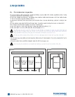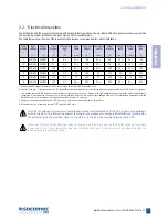
15
MODULYS Green Power
- Ref.: IOMMODGPXX01-GB 00
ENGLISH
5. CONNECTIONS
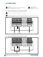
Mains and Aux Mains connected in common
5.4.2.
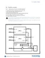
1. Confirm if the input and bypass input breaker (Q1 and Q4) are cut off.
2. Confirm if the manual bypass circuit breaker (Q5) is cut off.
3. Confirm if the output breaker (Q3) is cut off.
4. According to UPS model you have selected, make use of a suitable cable and lug.
5. Connect all cables to the right terminal or location as indicated).
6. Connect the parallel communication cable between UPS1 and UPS2.
7. Set both dip-switches to ON position.
The sum of AUX Mains cable length and OUTPUT cable length must be the same for each system. This regulation
prevents unbalanced load shared by two UPSs under by-pass mode (i.e.: AUX Mains cable 1 + OUTPUT cable 1
= AUX Mains cable 2 + OUTPUT cable 2). AUX Mains cable length is the same than Mains cable length.
For equipment with separate AUX Mains, it must be possible to make the neutral of the AUX Mains line electrically
common with the neutral of the main input feed line.
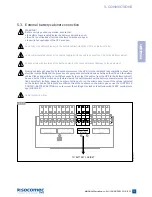
5.4.2-1
Wiring (Parallel Redundancy, Dual Input
Output
Output 1
Parallel Cable
Output 1
AUX
MAINS
MAINS
LOAD
AUX COMM
EXTERNAL
COUPLING
CABINET
Output
Aux mains
Aux mains
Bypass
breaker
Output
breaker
Mains
Mains
UPS1
UPS2
Parallel Port
Parallel Port
011 DR
WMODGP-XX
Summary of Contents for MODULYS Green Power
Page 33: ......


