102
Scope Multimeter Operations
Operations
The trigger point is indicated by a plus sign (+) on the scope grid. The plus sign can be dragged
across the grid with your finger or the stylus to roughly position it. The trigger controls allow you to
precisely position the trigger.
z
To adjust trigger controls:
1.
Select
Setup
from the Scope Multimeter toolbar.
The Scope Multimeter Preferences dialog box opens
2.
Tap
Trigger
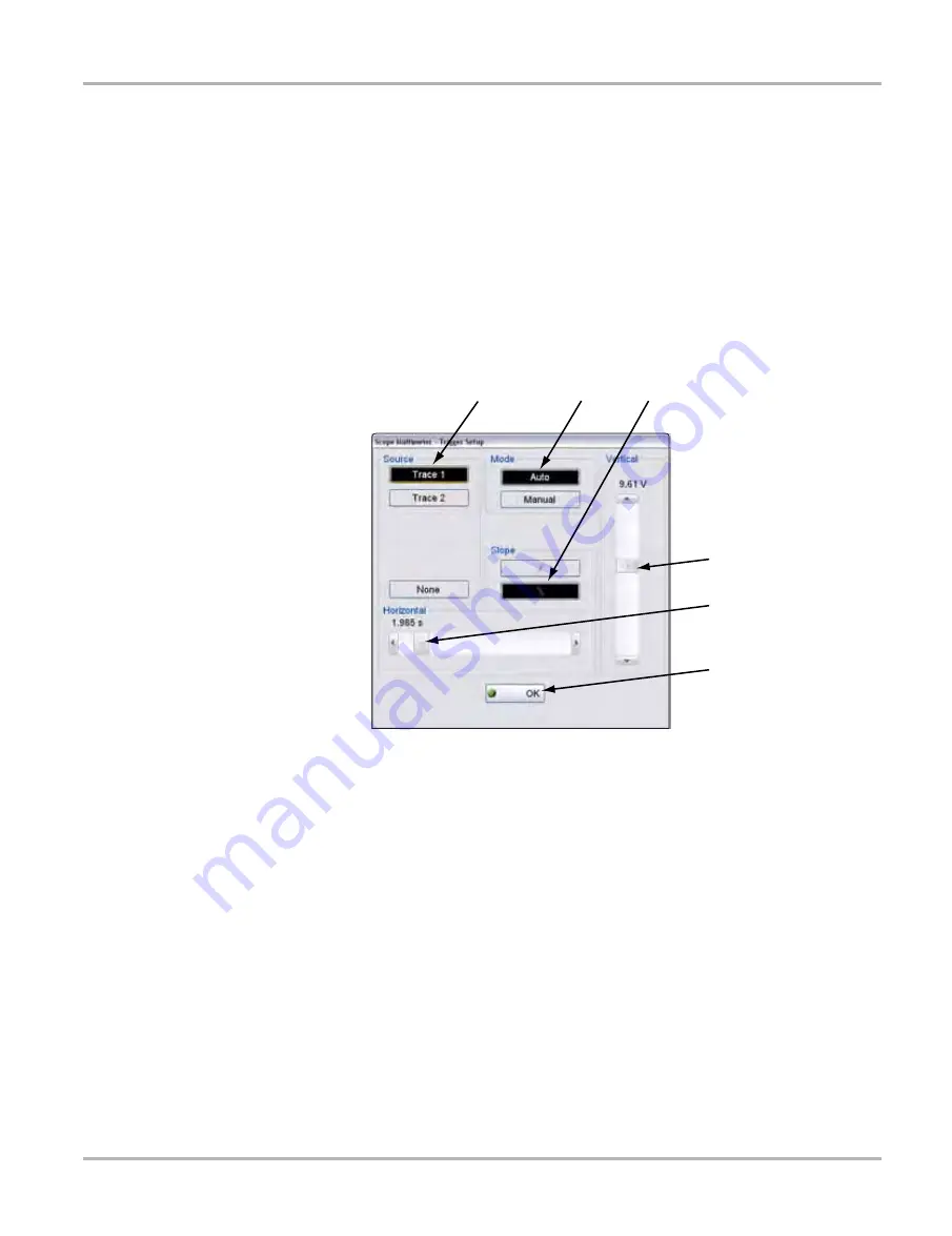
to open the Trigger Setup dialog box (
3.
Use the dialog box controls to establish the position for triggering.
4.
Select
OK
to close the dialog box.
5.
Select
Back
twice to close the Scope Multimeter Preferences dialog box.
1— Source
—selects the triggering event:
- Trace 1—sets conditions for the channel 1 signal.
- Trace 2—sets conditions for the channel 2 signal.
- None—switches triggering off.
2— Mode
—sets the method of triggering:
- Auto (automatic)—if a trigger is found, the waveform displays. If a trigger is not found
after several seconds, the waveform and a “trigger not found” message displays.
- Manual—if a trigger is found, the waveform displays. If a trigger is not found nothing
displays (no waveform and no message).
3— Slope
—sets triggering to the rising or falling edge of the signal.
4— Vertical position
—moves the trigger position up and down on the grid.
5— Horizontal position
—moves the trigger timing left and right on the grid
6— OK
—exits Trigger Setup
Figure 9-11 Trigger controls
Summary of Contents for VERDICT D7
Page 1: ...User Manual May 2011 EAZ0063L05C Rev B ...
Page 3: ...iii ...


