HOT LINE
®
Blood and Fluid Warmer
Technical Service Pack
22
S E C T I O N 3
T e c h n i c a l D e s c r i p t i o n
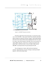
Digital Display
The temperature control thermistor is one of a pair, siamesed
together in the heater housing. The other of these provides a user
display of the recirculating solution temperature and, as we will see
later, protection in case of failure by the first thermistor.
The output from the display sensor thermistor is buffered by
U1.2, another LP324 quad op-amp device. It passes to U1.1, which is
a summing amplifier, combining the sensed voltage with the
buffered output from U1.4. This allows a degree of offset,
determined by R102, to be introduced for calibration purposes.
The buffered and calibrated voltage is scaled by R103/R104,
and presented to the digital LCD millivolt-meter module for display.
The window in the front case allows two digits to be seen by the
user, although the third digit (tenths of a degree) may be seen by
the technician when the case front is removed.
Q1
78L05
LCD Module
Alarm
Test
O'temp
Test
Control
Sensor
Display
Sensor
U1.4
U1.1
U1.2
J4
J1
U3.1
U2.2
U2.3
J201
U3.7
10
1
2
3
4
5
6
7
8
9
10
11
12
13
-t
-t
1
1
2
2
3
3
4
4
U3.6
VU
C
S
AA
X
5
8
4
11
9
6
10
7
R202
5k
Heat Control
R203
154k
R108
10M
R03/5
15k
OT Setpoint
R106
5k
LCD Cal
R102
5k
R107
34k
R504
15.4k
R603
15.4k
R607
178k
R601
11k
R03/3
15k
R01/1
15k
R602
15.4k
R01/6
15k
R605
15.4k
R103
105k
R104
1k
J101
R606
11k
R01/7
15k
R204
1M
R02/4
15k
R03/8
15k
R01/8
15k
R01/9
15k
R201
16.5k
R206
3.15k
R207
15.4k
CR201
1N4001
C201
22 F
µ
C101
47 F
µ
U1.3
12
11
4
13
14
5
9
9
3
5
1
6
11
10
10
10
2
6
7
5
7
8
8
1
7
15
2
3
1
U2.1
CR202
Green
GM-HL90_8306-A
Figure 3 - 3: HOTLINE
®
Temperature Monitoring Circuits
Summary of Contents for level 1 HOTLINE HL-90
Page 1: ......
Page 14: ...Introduction Specifications Blood and Fluid Warmer ...
Page 20: ...Sub Assemblies Blood and Fluid Warmer ...
Page 28: ...Technical Description Blood and Fluid Warmer ...
Page 45: ...Disassembly Procedures Blood and Fluid Warmer ...
Page 58: ...Blood and Fluid Warmer Maintenance Testing and Calibration ...
Page 83: ...Troubleshooting Blood and Fluid Warmer ...
Page 88: ...Spare Parts Blood and Fluid Warmer ...
Page 96: ...Rounding Off Blood and Fluid Warmer ...
Page 106: ...Appendix 1 Circuits Blood and Fluid Warmer ...
Page 110: ...Appendix 2 PCB Layout Blood and Fluid Warmer ...
Page 115: ...Appendix 3 Symbols Glossary Blood and Fluid Warmer ...
Page 118: ...Appendix 4 Frequently Asked Questions Information Bulletins Blood and Fluid Warmer ...
Page 132: ...Ndjg CdiZh 9 V gVbh ...


