


HOT LINE
®
Blood and Fluid Warmer
Technical Service Pack
29
S E C T I O N 3
T e c h n i c a l D e s c r i p t i o n
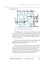
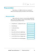
Interlock Alarm
The interlock switch is a simple microswitch which is operated
by the insertion of the warming set into the twin socket. If you were
to switch the pump on with no warming set connected, the results
would not be catastrophic, nor particularly dangerous, but they
could be awfully messy!
Therefore, if the Interlock Switch is not made, the pump (and
heater) will not run. The flashing LED lets you know why the
HOTLINE
®
is refusing to co-operate.
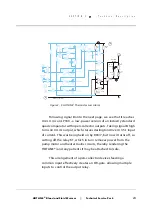
This part of the circuit has a fail-safe action that might mislead
you if you’re faultfinding. U03.2 is kept turned on by the pull-up
resistor R03/1 so that if there is a fault in the interlock switch
off-board wiring, or the J2 connector isn’t fully connected, the alarm
is defaulted ON. You need a good continuous circuit through J2 to
allow U3.7 to pull U03.2 low and turn the alarm state off.
Float
Switch
Float
System
Normal
Interlock
Switch
Interlock
Overtemp
J3
J2
U4.2
U4.1
U4.3
U4.4
Relay
K1
U3.3
Piezo
U3.2
U3.4
U3.5
U2.4
S
X
AA
10
VU
15
12
3
R305
100k
R03/7
15k
R03/1
15k
R03/2
15k
R302
8.2M
R307
15.4k
R301
722R
R02/2
15k
R02/3
15k
R01/2
15k
R03/6
15k
R03/9
15k
R304
100k
R308
15.4k
R306
15.4k
CR302 Red
CR301 Red
CR303 Red
R 2
270R
CR 401
Green
R401
1k
C302
10 F
µ
C301
0.1 F
µ
3
2
14
4
13
6
5
12
7
10
11
12
13
5
9
8
12
3
3
1
1
2
2
2
4
15
14
13
8
14
9
1
GM-HL90_8312-A
Figure 3 - 10: HOTLINE
®
Warming Set Interlock Alarm
Summary of Contents for level 1 HOTLINE HL-90
Page 1: ......
Page 14: ...Introduction Specifications Blood and Fluid Warmer ...
Page 20: ...Sub Assemblies Blood and Fluid Warmer ...
Page 28: ...Technical Description Blood and Fluid Warmer ...
Page 45: ...Disassembly Procedures Blood and Fluid Warmer ...
Page 58: ...Blood and Fluid Warmer Maintenance Testing and Calibration ...
Page 83: ...Troubleshooting Blood and Fluid Warmer ...
Page 88: ...Spare Parts Blood and Fluid Warmer ...
Page 96: ...Rounding Off Blood and Fluid Warmer ...
Page 106: ...Appendix 1 Circuits Blood and Fluid Warmer ...
Page 110: ...Appendix 2 PCB Layout Blood and Fluid Warmer ...
Page 115: ...Appendix 3 Symbols Glossary Blood and Fluid Warmer ...
Page 118: ...Appendix 4 Frequently Asked Questions Information Bulletins Blood and Fluid Warmer ...
Page 132: ...Ndjg CdiZh 9 V gVbh ...