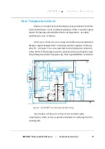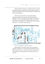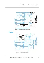
HOT LINE
®
Blood and Fluid Warmer
Technical Service Pack
20
S E C T I O N 3
T e c h n i c a l D e s c r i p t i o n
derived from a conventional step-down transformer. After
rectification and smoothing, the supply is regulated to a nominal 10
volts by U501, an LM317T integrated regulator. Resistors R501 and
R502 set the exact output voltage level.
NOTE:
The HOTLINE
®
is NOT a Class 2 double-insulated device, and
must be connected with a good earth connection to ensure
patient and operator safety.
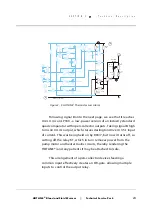
Control Circuit
The control sensor is one of a “siamese twin” pair of
thermistors submerged in the recirculating solution flow as it leaves
the heater. At normal operating temperatures, the thermistors each
have a resistance of about 15k, and this decreases roughly linearly
with increasing temperature.
Q1
78L05
LCD Module
Alarm
Test
O'temp
Test
Control
Sensor
Display
Sensor
U1.4
U1.1
U1.2
J4
J1
U3.1
U2.2
U2.3
J201
U3.7
10
1
2
3
4
5
6
7
8
9
10
11
12
13
-t
-t
1
1
2
2
3
3
4
4
U3.6
VU
C
S
AA
X
5
8
4
11
9
6
10
7
R202
5k
Heat Control
R203
154k
R108
10M
R03/5
15k
OT Setpoint
R106
5k
LCD Cal
R102
5k
R107
34k
R504
15.4k
R603
15.4k
R607
178k
R601
11k
R03/3
15k
R01/1
15k
R602
15.4k
R01/6
15k
R605
15.4k
R103
105k
R104
1k
J101
R606
11k
R01/7
15k
R204
1M
R02/4
15k
R03/8
15k
R01/8
15k
R01/9
15k
R201
16.5k
R206
3.15k
R207
15.4k
CR201
1N4001
C201
22 F
µ
C101
47 F
µ
U1.3
12
11
4
13
14
5
9
9
3
5
1
6
11
10
10
10
2
6
7
5
7
8
8
1
7
15
2
3
1
U2.1
CR202
Green
GM-HL90_8305-A
Figure 3 - 2: HOTLINE
®
Temperature Control Circuits
Summary of Contents for level 1 HOTLINE HL-90
Page 1: ......
Page 14: ...Introduction Specifications Blood and Fluid Warmer ...
Page 20: ...Sub Assemblies Blood and Fluid Warmer ...
Page 28: ...Technical Description Blood and Fluid Warmer ...
Page 45: ...Disassembly Procedures Blood and Fluid Warmer ...
Page 58: ...Blood and Fluid Warmer Maintenance Testing and Calibration ...
Page 83: ...Troubleshooting Blood and Fluid Warmer ...
Page 88: ...Spare Parts Blood and Fluid Warmer ...
Page 96: ...Rounding Off Blood and Fluid Warmer ...
Page 106: ...Appendix 1 Circuits Blood and Fluid Warmer ...
Page 110: ...Appendix 2 PCB Layout Blood and Fluid Warmer ...
Page 115: ...Appendix 3 Symbols Glossary Blood and Fluid Warmer ...
Page 118: ...Appendix 4 Frequently Asked Questions Information Bulletins Blood and Fluid Warmer ...
Page 132: ...Ndjg CdiZh 9 V gVbh ...


