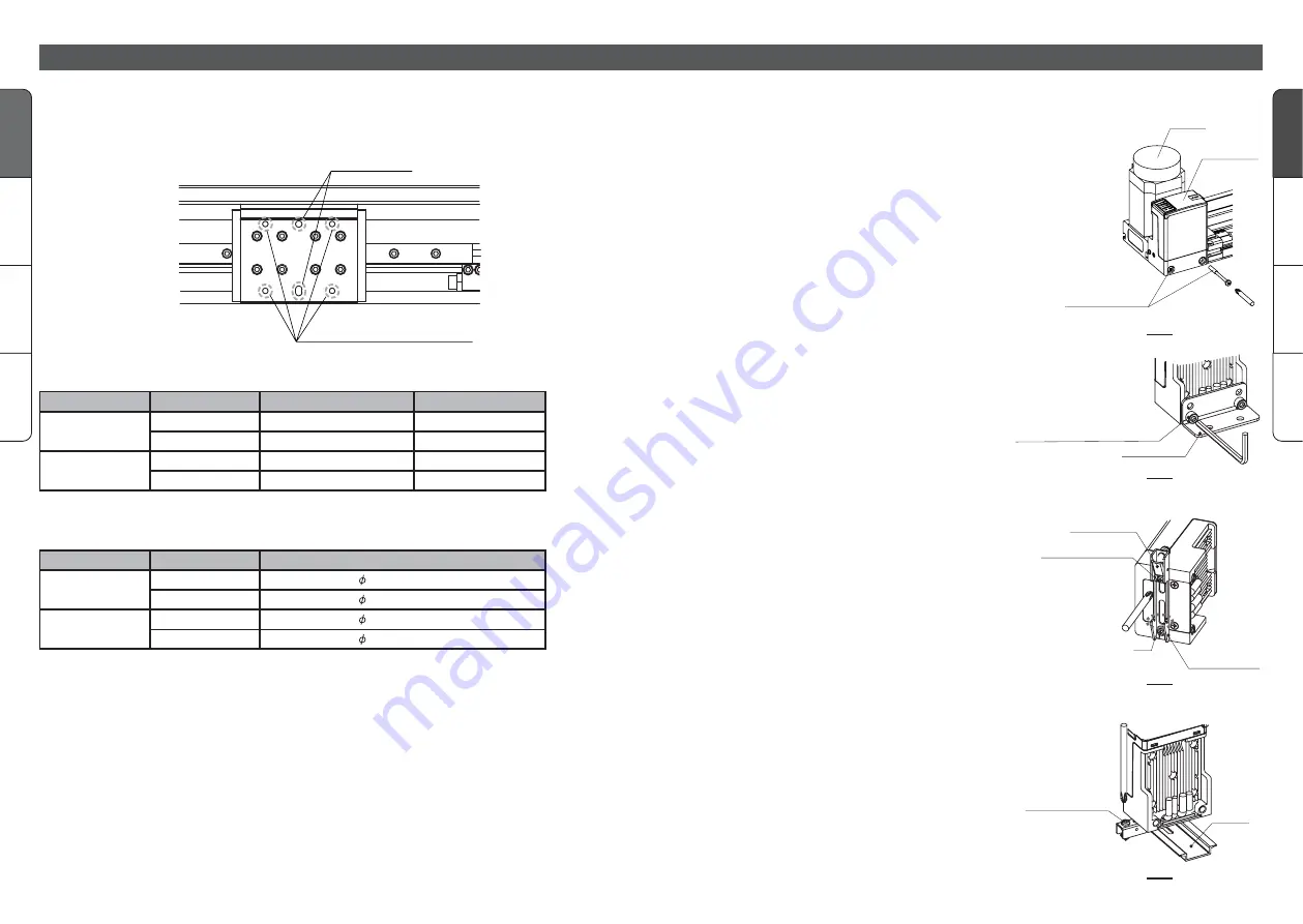
Knock pin hole
9
Gener
al
3 positions
5 positions
Gener
al
8
Gener
al
3 positions
5 positions
Gener
al
Installation (continue)
Installation of work tap
Taps hole to installation of work
Knock pin hole
Precautions for installation
•Do not operate the actuator outside operating temperature range.
•Do not install the actuator in the place which may be used as foot base.
•Keep flatness following mechanical accuracy or equivalent reference for the face where the
actuator is installed.
Also, confirm the flatness is within 0.1/500mm
Installation of work
Use 4 taps on the top of slider for installation of work.
Also, if necessary, utilize knock pin hole as well.
Nominal of actuator
16
25
Threaded hole dimension
M4 depth 7mm
M5 depth 9mm
Effective length
4 to 7mm
5 to 9mm
•Select screw which enables effective length of thread to enter.
Nominal of actuator
16
25
Hole diameter and width of oval hole
( )4 H7 depth 5mm
( )5 H7 depth 5mm
Mounting controller (When controller separated type is used)
Mounting screw (M5)
Tightening torgue 1.3 to 1.4N
•
m
L type bracket
Controller
Motor
Mounting screw
(M4)
Mounting by L type bracket
Mount the optional L type bracket on the main
unit using the two mounting screws M5X8L and
install on the facility using hexagon socket head
cap screws as shown in fig. 2.
Clamp bracket
DIN rail
mount bracket
Mounting screw(M3)
Tightening torgue
0.5 to 0.7N
•
m
A
Mounting by DIN rail bracket
Use set screw to mount optional DIN rail mount
bracket to the body.
When mounting, lower the clamp bracket as in
fig. 3.
Please be noted that some tools may interfere
with clamp bracket.
DIN rail
Tightening torgue
0.4 to 0.6N
•
m
Clamp screw(M4)
When setting to DIN rail, place A of fig. 3 into
DIN rail.
While pushing it, fix it by the clamp of screw in fig.
4.
Inadequate pushing may cause falling of parts.
Direct mounting
Use M4 mounting screw shown in fig. 1 or M5
tap hole to mount the controller.
How to remove controller
Loosen M4 mounting screw shown in fig. 1 and
remove the controller.
fig. 1
fig. 2
fig. 3
fig. 4
Model
E-MY2C
E-MY2H
16
25
M5 depth 9mm
M8 depth 12mm
5 to 9mm
8 to 12mm
E-MY2HT
Model
E-MY2H
16
25
( )5 H7 depth 5mm
( )6 H7 depth 8mm
E-MY2HT
•A knock pin is attached only to E-MY2H and E-MY2HT.


