background image


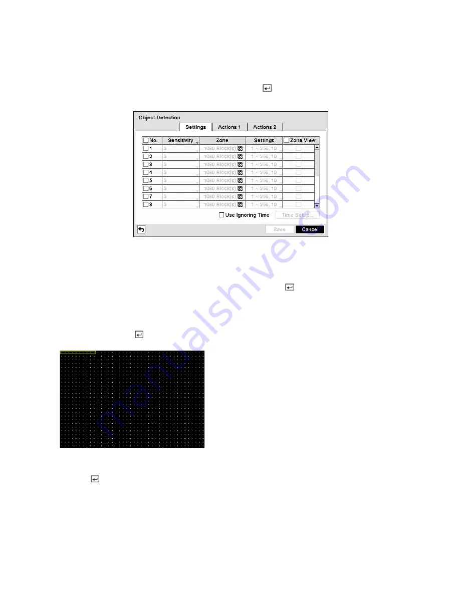
Object Detection Screen 

 
Highlight 

Object Detection

 in the Event menu and press the   button.  The 

Object Detection

 setup 

screen appears.


Figure 86 — Object Detection Settings screen. 

 
Object detection can be turned On or Off for each camera. 
 
Highlighting the box under the 

Sensitivity

 heading and pressing the   button allows you to adjust the 

DVR’s sensitivity to object detection.  There are five settings with 

1

 being the least sensitive and 

5

 being 

the most sensitive. 
 
You can define the area of the image where you want to detect object.  Highlight the box under the 

Zone


heading, and press the   button.  The 

Object Detection Zone

 screen displays. 


Figure 87 — Object Detection Zone screen.


The 

Object Detection Zone

 screen is laid over the video 

for the selected camera.  You can set up object detection 
zones by selecting or clearing blocks. 


NOTE:  You can set up object zones one block at a 
time in groups of 10 individual block groups.  A block 
group is positioned within the image area using the 
Up and Down arrow buttons, and individual blocks 
within the block groups are selected or cleared using 
the camera buttons. 


Press the   button to display the menu screen.  The menu on the setup screen has the following functions: 

Summary of Contents for STR-1690

Page 1: ...User Manual Smartec sixteen channel DVR STR 1690 www smartec security eu ...

Page 2: ...LE PROTECTION AGAINST HARMFUL INTERFERENCE WHEN THE EQUIPMENT IS OPERATED IN A COMMERCIAL ENVIRONMENT THIS EQUIPMENT GENERATES USES AND CAN RADIATE RADIO FREQUENCY ENERGY AND IF NOT INSTALLED AND USED IN ACCORDANCE WITH THE INSTRUCTION MANUAL MAY CAUSE HARMFUL INTERFERENCE TO RADIO COMMUNICATIONS OPERATION OF THIS EQUIPMENT IN A RESIDENTIAL AREA IS LIKELY TO CAUSE HARMFUL INTERFERENCE IN WHICH CAS...

Page 3: ...C If the equipment has been exposed to rain or water D If the equipment does not operate normally by following the operating instructions adjust only those controls that are covered by the operating instructions as an improper adjustment of other controls may result in damage and will often require extensive work by a qualified technician to restore the equipment to its normal operation E If the e...

Page 4: ...4 Normally Closed Normally Open 6 ARI Alarm Reset In 6 Connecting to the RS485 Port 6 Connecting to the RS232 Port 7 Connecting to the USB Ports 7 Connecting to the Network Port 8 Connecting to the Ultra Wide SCSI Port 8 Factory Reset 8 Connecting the Power Cord 9 Chapter 3 Configuration 11 Front Panel Controls 11 HDD Rack 12 Power LED 13 Network LED 13 Mirroring LED 13 HDD LED 13 ODD Button 13 St...

Page 5: ...en 17 System Information 18 Date Time Setup 21 Storage Screen 23 User Setup Screen 26 Shutdown Screen 28 Logout Screen 28 Network Notification Setup 28 Network Screen 29 LAN Setup Screen 29 DVRNS Setup 32 WebGuard Setup 34 Notification Setup 34 Configuring Devices 36 Camera Setup Screen 36 Alarm Out Screen 38 Display Screen 39 Remote Control Screen 42 Recording Settings 42 Record Screen 43 Schedul...

Page 6: ...ent 74 Event Monitoring 75 Covert Camera 75 Spot Monitoring 75 Triplex Function 76 Using a Mouse 77 Recording Video 78 Recording Audio 79 Playing Recorded Video 79 Rewind Button 79 Fast Forward Button 79 Backward Button 79 Forward Button 79 Search Stop Button 79 Camera Buttons 1 to 16 80 Display Button 80 Zoom Button 80 Shuttle Ring 80 Jog Dial 80 Searching Video 81 Go to the Date Time 82 Bookmark...

Page 7: ...ows 98 93 Appendix B Reviewing Video Clips 94 Appendix C WebGuard 96 Web Monitoring Mode 97 Web Search Mode 98 Appendix D Time Overlap 97 Appendix E Troubleshooting 101 Appendix F Connector Pin Outs 102 I O Connector Pin Outs 102 RS485 Connector Pin Outs 102 Appendix G Map of Screens 103 Appendix H System Log Notices 104 Appendix I Error Code Notices 105 Appendix J Specifications 106 ...

Page 8: ...e control 12 Figure 22 Hard Disk Drive Rack 12 Figure 23 Login screen 17 Figure 24 Setup screen 17 Figure 25 Virtual Keyboard 18 Figure 26 Information screen 18 Figure 27 Upgrade screen 19 Figure 28 Setup Import screen 19 Figure 29 Setup Export screen 20 Figure 30 System Log screen 20 Figure 31 Date Time setup screen 21 Figure 32 Holiday setup screen 22 Figure 33 Time Sync screen 22 Figure 34 Stor...

Page 9: ...4 Alarm In Settings screen 49 Figure 75 Alarm In Actions 1 screen 50 Figure 76 Alarm In Notify menu 50 Figure 77 Alarm In Actions 2 screen 51 Figure 78 Motion Detection Settings screen 51 Figure 79 Motion Detection Sensitivity screen 52 Figure 80 Motion Detection Zone screen 52 Figure 81 Motion Detection Zone menu 52 Figure 82 Daytime Setup screen 53 Figure 83 Motion Detection Min Blocks screen 53...

Page 10: ... Mouse menu 77 Figure 116 Mouse Display menu 78 Figure 117 Mouse Playback controls 80 Figure 118 Search menu 81 Figure 119 Go to the Date Time screen 82 Figure 120 Bookmarks screen 82 Figure 121 Calendar Search screen 83 Figure 122 Event Log Search screen 84 Figure 123 Event Log Search Option screen 84 Figure 124 Text In Search screen 86 Figure 125 Text In Search Option screen 86 Figure 126 Motion...

Page 11: ...event Alarm Motion and Panic y Two way Audio Communications y 16 Channel Audio Recording and 1 Channel Audio Playback y Text Input for ATM and POS y Alarm Connections Include 16 Inputs 16 Outputs and Reset Input y Built in Alarm Buzzer y Live or Recorded Video Access via Ethernet y Time Synchronization using industry standard protocol y Built in DVD RW Drive y Self diagnostics with automatic notif...

Page 12: ... being written on the storage device can be lost or corrupted Your DVR supports disk mirroring functions to prevent any unexpected loss of recorded video data that might be caused by disk damage or corruption Your DVR uses a proprietary encryption scheme making it nearly impossible to alter video You can view video and control your DVR remotely by connecting via Ethernet There is a SCSI port that ...

Page 13: ...for Adding Hard Disk Drives y Screws for Attaching SCSI Connector y Hard Disk Drive Rack Key Required Installation Tools No special tools are required to install the DVR Refer to the installation manuals for the other items that make up part of your system Figure 2 Rear panel Video Input Video Loop Through Video Out Audio In Out Alarm Input Output RS485 Port RS232 Port USB Port Ethernet Port SCSI ...

Page 14: ... are auto terminated Do NOT connect a cable to the Loop BNC unless it is connected to a terminated device because it will cause poor quality video Connecting the Monitor Figure 5 Video Out connectors Connect the main monitor to either the Video Out or SVHS Out connector NOTE If your main monitor has an SVHS input use it because it will give you better quality video display Up to four Spot monitors...

Page 15: ...E The DVR does not have amplified audio output so you will need a speaker with an amplifier The DVR does not have a pre amplifier for audio input so the audio input should be from an amplified source not directly from a microphone Connecting Alarms NOTE To make connections on the Alarm Connector Strip press and hold the button and insert the wire in the hole below the button After releasing the bu...

Page 16: ...mally Closed Normally Open Figure 10 Relay Alarm Output connectors Connect the device to the C and NC Normally Closed connectors or C and NO Normally Open connectors NC NO is a relay output which sinks 0 5A 125V and 1A 30V ARI Alarm Reset In Figure 11 Alarm Reset Input connectors An external signal to the Alarm Reset In can be used to reset both the Alarm Out signal and the DVR s internal buzzer M...

Page 17: ...nt USB connectors Figure 15 Rear USB connector Three USB ports are provided to connect external hard disk CD RW or flash drives for video clip copying or system upgrades One USB port is on the rear panel and the other two are on the front panel Position external drives close enough to the DVR so that you can make the cable connections usually less than 6 feet Use the USB cable provided with the ha...

Page 18: ...ID cable to the high density 68 pin female UltraWide SCSI port The length of SCSI cable should not exceed 5 feet 1 5 meters You can connect up to 8 UltraWide SCSI devices with SCSI IDs set from 0 to 15 except for 7 which is assigned as the Host ID NOTE The SCSI bus must be terminated otherwise the DVR will not operate properly NOTE When using low speed SCSI devices the maximum recording speed decr...

Page 19: ... left of the RS485 port 4 Hold the switch until all the LEDs on the front panel are lit NOTE When the DVR successfully resets to factory defaults all the LEDs on the front panel flash five times 5 Release the reset switch All of the DVR s settings are now at the original settings it had when it left the factory Connecting the Power Cord Figure 19 Power cord connector Connect the AC power cord to t...

Page 20: ...uttons Shuttle Ring Jog Dial Many of the buttons on the front panel have multiple functions The buttons on the infrared remote control while laid out differently perform the same functions as those on the front panel The following describes each button and control Take a few minutes to review the descriptions You will use these to initially set up your DVR and for daily operations NOTE The infrare...

Page 21: ...Figure 21 Infrared remote control HDD Rack Figure 22 Hard Disk Drive Rack ...

Page 22: ...g video on each hard disk drive A red LED flickers when the hard disk drive is not operating normally or not installed on the system and a green LED flickers when the hard disk drive is operating normally When the DVR is in the disk mirroring mode an orange LED flickers during disk resynchronization and turns to a green LED when resynchronization is complete ODD Button Pressing the ODD button will...

Page 23: ...increase or decrease the number s value The arrow buttons are also used to control Pan and Tilt when in the PTZ mode When in the PIP display format pressing the Up and Down arrow buttons moves the position of the small screen counter clockwise and clockwise and pressing the Left and Right buttons moves through screen pages Menu Button Pressing the button enters the Setup screen You will need to en...

Page 24: ...can opt to have that Spot Monitor display a single camera or all cameras sequentially The infrared remote control allows you to go directly to the individual Spot Monitor menus Playback Buttons y Play Pause Pressing the button plays back images at regular speed Pressing the button while in the Playback mode pauses the video The screen displays and the status display panel displays when the DVR is ...

Page 25: ...rns to the center position when released Turning the ring clockwise plays video forward Turning the ring counterclockwise plays video backward Playback speed varies with the amount the ring is turned The playback speeds are x0 5 and When you release the ring it snaps back to the center position and the video pauses Jog Dial When in the playback mode you can play video forward image by image by tur...

Page 26: ...o reset that screen to its default settings Press the Menu button to enter the setup screens The Login screen appears Figure 23 Login screen Select a User and enter the password by pressing the appropriate combination of Camera number buttons and then the button There is no default password when logging in the admin user for the first time NOTE To assure the secure management of the system setting...

Page 27: ...urn Special characters are commonly used by text input devices and will be useful when performing Text In Searches System Information Highlight Information and press the button The Information screen appears Figure 26 Information screen In the Information screen you can name the site location assign a System ID number select the language the screens are displayed in display software version number...

Page 28: ... software package Highlighting the Cancel button and pressing the button will close the window without upgrading the software If the upgrade package file is not installed on the DVR properly you will get an error message The system restarts automatically after completing the upgrade Figure 27 Upgrade screen NOTE The Upgrade button will be deactivated if the hard disk drive has not been formatted a...

Page 29: ...scroll through the log pages by using the Up and Down arrows or you can go directly to a log page by entering the log page number in the box at the bottom left of the screen Highlight Close and press the button to exit the screen The box beside Recorded Data From To displays the time information of recorded data Highlighting Clear All Data and pressing the button will clear all video data You will...

Page 30: ...irst box beside Time and press the button The individual sections of the time will highlight Use the Up and Down arrow buttons to change the number Use the Left and Right arrow buttons to move between hour minutes and seconds Once you have the correct time press the button Highlight the Format box beside Time and press the button Select from the three available time formats and press the button to...

Page 31: ... updated once the current year s holiday has passed Highlighting the Time Sync tab causes the Time Sync screen to display You can set up time synchronization between the DVR and standard time servers that are available in most time zones and countries or between the DVR and another DVR Figure 33 Time Sync screen Highlight the box beside Automatic Sync and press the button This toggles between On a...

Page 32: ...ation screen The information in the Type column describes the storage device The capacity of the storage device is displayed in the Capacity column The Format column displays whether the device is used for recording Record or archiving Archive Not Using indicates the device is not used for either recording or archiving Unformatted indicates the device is not formatted indicates when the device has...

Page 33: ...from the DVR highlight Don t Use first and then disconnect the device CAUTION Do NOT disconnect the USB cable or the power from the device while copying video clips If the USB cable is disconnected while copying video clips archived data might be lost Highlight the box under Mirroring Setup and set up disk mirroring between the source disk and the destination disk selected from the list of interna...

Page 34: ...ead from the storage device y N A Storage conditions are normal however the S M A R T monitoring is not working or supported NOTE When the storage condition is Bad the Event Status Storage screen displays and you can check the storage condition for details Once the Bad message displays replacing the hard disk drive is recommended usually within 24 hours NOTE Temperature and S M A R T information w...

Page 35: ... all of the User Names within that group are hidden To collapse or expand a group highlight the column in front of the desired group and press the button Highlighting a Group Name and pressing the button allows you to change the authority levels assigned to the group CAUTION Write down the new password and save it in a secure place If the password is forgotten the unit must be reset using the Fact...

Page 36: ...l the PTZ camera on a local system or a PC running RAS y Alarm Out Control The user can reset the DVR s outputs including the internal buzzer during an alarm by pressing the Alarm button on a local system or alarm out control button on a PC running RAS y Covert Camera View The user can view video from cameras set as Covert while in the Live Monitoring or Search mode on a local system or a PC runni...

Page 37: ...s Shutdown Screen Highlight Shutdown in the System menu and press the button The Shutdown screen displays asking you to confirm whether or not you want to shut the system down After selecting Shutdown and pressing the button a screen will appear telling you when it is safe to disconnect power Figure 41 Shutdown screen Logout Screen Highlight Logout in the System menu and press the button The Logou...

Page 38: ... Quality Highlight the box beside Resolution and press the button You can select the Resolution from High Half D1 and Standard CIF Press the button to set the Resolution NOTE The higher Quality and Resolution settings require higher Transfer Speed settings The transfer speed you set is the maximum speed Depending on the network environment this speed may not be achieved The DVR supports two way au...

Page 39: ... Up and Down arrow buttons to increase or decrease the number The factory default LAN settings are IP Address 192 168 1 129 Gateway 192 168 1 254 Subnet Mask 255 255 255 0 Highlight the box beside DNS Server Press the Up and Down arrow buttons to set the IP address of the DNS server If you set up the DNS Server the domain name of the DVRNS server instead of the IP address can be used during the DV...

Page 40: ...tings NOTE Do NOT use the same port number for two different programs otherwise the DVR cannot be connected with the PC running RAS or WebGuard CAUTION When changing the port settings you must change the port settings on the PC running RAS or WebGuard as well Refer to the RAS manual for details Selecting DHCP from the Type and highlighting Save button reads the current IP address of the DVR config...

Page 41: ...nection NOTE Entering the ID and Password and highlighting OK reads the current IP address of the DVR configured by the ADSL network NOTE If the DVR is configured for DHCP or an ADSL network the IP address of the DVR might change whenever the unit is turned on DVRNS Setup Highlight the DVRNS tab and the DVRNS screen displays Figure 49 DVRNS setup screen NOTE When LAN settings have been changed set...

Page 42: ...ion device refer to the NAT manufacturer s instructions for the proper network settings Highlight the box beside DVR Name and press the button A virtual keyboard appears allowing you to enter the DVR name to be registered on the DVRNS server Highlight the Check box and press the button to check whether or not the name you entered can be used NOTE The DVR name you entered should be checked by selec...

Page 43: ...ard by using the Up and Down arrow buttons to increase or decrease the numbers You can save your Network changes by highlighting Save and pressing the button Selecting Cancel exits the screen without saving the changes Notification Setup The DVR can be set up to send an email or to contact a computer running RAS Remote Administration System when an event occurs Highlight Notification in the Networ...

Page 44: ...ess the button An Authentication screen appears Highlight Use and press the button to toggle between On and Off Highlight the box beside User Password and press the button A virtual keyboard appears allowing you to enter the user ID and password Figure 52 Authentication setup screen Highlight the box beside Sender and enter the sender s e mail address Use the virtual keyboard to enter the e mail a...

Page 45: ...the screen without saving the changes Configuring Devices You can configure the video audio alarm display and remote control devices connected to the DVR Figure 54 Device menu Camera Setup Screen Highlight Camera in the Devices menu and press the button The Camera setup screen appears Figure 55 Camera setup screen You can turn the camera number On or Off and you can change the Title of each camera...

Page 46: ...l need to connect the camera to the RS232 or RS485 connector on the back of the DVR following the camera manufacturer s instructions Figure 57 PTZ Device list You can assign IDs to each camera by highlighting the box under the ID heading and pressing the button Change the number by highlighting it and using the Up and Down arrow buttons to increase and decrease the number The PTZ ID number can be ...

Page 47: ...ting the boxes under the Type heading allows to set the alarm output for NO or NC normally open or normally closed Highlighting the box beside Dwell Time and pressing the button allows you to set the dwell time of the alarm output Dwell times range from 5 seconds to 15 minutes Highlighting the Schedule tab causes the Schedule screen to display Figure 60 Alarm Out Schedule screen You can add and ed...

Page 48: ... schedule You can save your Alarm Out changes by highlighting Save and pressing the button Selecting Cancel exits the screen without saving the changes Display Screen Highlight Display in the Devices menu and press the button The Display screen allows you to select what information will be displayed on the monitor Figure 61 Display OSD screen Highlighting an item and pressing the button toggles th...

Page 49: ...ch the DVR can play live audio You can adjust the transparency of the setup screens by highlighting Transparency and using the Left and Right arrow buttons Highlighting OSD Margin and pressing the button displays how OSD text will be displayed on the monitor You can adjust the horizontal and vertical margins so that text and icons will not be hidden beyond the edges of the monitor Figure 62 OSD Ma...

Page 50: ...he bottom right window as the cameo NOTE Sequence cannot be used in the 4x4 display mode You can adjust the display dwell time by highlighting the box beside Interval and pressing the button You can select dwell intervals ranging from 1 second to 1 minute Highlight Event Monitoring On and press the button Pressing the button toggles between On and Off When it is On the DVR will display the camera ...

Page 51: ...he correct Baud Rate Parity Data Bits and Stop Bits for the device you are connecting to the DVR Highlight the box beside Remote Control Product and select the device from the list You can save your Remote Control settings by highlighting Save and pressing the button Selecting Cancel exits the screen without saving the changes Recording Settings Your DVR offers a variety of flexible recording mode...

Page 52: ...o 99 days The DVR automatically deletes video recorded earlier than the user defined period under three conditions at midnight whenever the system reboots or whenever the user changes the Auto Deletion settings Selecting Never will disable the Auto Deletion function Highlighting Use Real Time High Resolution Record and pressing the button toggles between On and Off When set to On the DVR can recor...

Page 53: ... not pressed to stop the panic recording You can set the dwell from 5 minutes to 1 hour Select No Limit if you want to stop panic recording manually Highlighting the Panic Recording ips and pressing the button allows you to set the images per second for Panic recording You can select from 0 25 to 30 00 images per second NOTE When Real Time High Resolution Record is set to Off the maximum ips for P...

Page 54: ... Hol and All Highlight the box under the Range heading and press the button to change the time range that the scheduled recording will take place The smallest time segment you can use is 30 minutes Highlight the box under the Mode heading and press the button to change the recording mode that will be used Choose from No Record Time Event and Time Event When the DVR is in the No Record mode it will...

Page 55: ...ems you will get a confirmation screen asking you to continue scheduling even though one of two associated channels will be automatically removed from scheduling if the other channel is set to record 30 ips with Very High D1 resolution when in the Real Time High Resolution Record mode NOTE When in the Real Time High Resolution Record mode pre event settings for one of two associated channels will ...

Page 56: ...25 to 30 00 ips 25 00 ips PAL image quality can be selectable from Super High High Standard and Basic and image resolution can be selectable from Very High D1 High Half D1 and Standard CIF NOTE When in the Real Time High Resolution Record mode you cannot configure pre event recording for one of two associated channels channel 1 and channel 2 channel 3 and channel 4 and channel 15 and channel 16 if...

Page 57: ...eaving the default checkmarks in the Last Archived and Continue boxes If you wish to enter specific times and dates in From and To toggle the checkmarks Off and then enter the time and date Highlight Recycle and press the button to toggle between On and Off When Recycle is On and the storage device is full the newest archived video data will overwrite the oldest archived data When Recycle is Off t...

Page 58: ...p on the back of the DVR has inputs associated with each alarm You can set up each input on the Alarm In screen You can turn each input On or Off by highlighting the alarm number and pressing the button Each input can be given a title Highlight the desired Title box and press the button A virtual keyboard appears allowing you to enter a title name Each input can be set as NO normally open or NC no...

Page 59: ... detects an input on the associated alarm input You can also set the DVR s internal buzzer to sound NOTE For the Alarm Out action the alarm output and beep you select should be set to the Event mode in the Alarm Out setup screen Schedule tab Highlight the desired box under the Notify heading and press the button The Alarm In Notify menu appears Figure 76 Alarm In Notify menu You can toggle the ent...

Page 60: ...pears Each SPOT monitor can be associated with a camera The DVR will display the associated camera on the SPOT monitor whenever it detects an input on the associated alarm input You can save your Alarm In changes by highlighting Save and pressing the button Selecting Cancel exits the screen without saving the changes Motion Detection Screen Highlight Motion Detection in the Event menu and press th...

Page 61: ...display the menu screen The menu on the setup screen has the following functions Select Activates highlighted blocks to detect motion Clear Deactivates highlighted blocks so that they will not detect motion Reverse Activates inactive highlighted blocks and deactivates active highlighted blocks Select All Activates all blocks to detect motion Clear All Deactivates all blocks so that they will not d...

Page 62: ...tion zone of video will be displayed in green Any detected motion within the zone will be displayed in red Viewing motion only enables in full screen mode Highlight the Actions 1 and Actions 2 tabs and the Motion Detection Actions 1 and Actions 2 screens display Figure 84 Motion Detection Actions 1 screen The DVR can be set to react to motion detection differently for each camera Each camera can b...

Page 63: ...le the individual items On and Off by highlighting that item and pressing the button Highlight OK and press the button to accept your changes NOTE For the Notify action the notify item you select should be enabled in the Notification setup screen and the DVR should be registered in the RAS Remote Administration System Figure 85 Motion Detection Actions 2 screen Highlight the desired box under the ...

Page 64: ...here you want to detect object Highlight the box under the Zone heading and press the button The Object Detection Zone screen displays Figure 87 Object Detection Zone screen The Object Detection Zone screen is laid over the video for the selected camera You can set up object detection zones by selecting or clearing blocks NOTE You can set up object zones one block at a time in groups of 10 individ...

Page 65: ...ed settings the current image will be automatically set as the reference image if there is no registered reference image Highlighting the box under the Settings heading and pressing the button allows you to adjust the minimum number and maximum number of detection blocks that must be activated to trigger an object alarm You can also set the time duration for detecting the difference between the re...

Page 66: ...ent recording mode in the Record Schedule setup screen Highlight the box under the Alarm Out heading and press the button A list of Alarm Outputs appears You can associate as many Alarm Outs with that camera as you wish When the DVR detects an object on the selected camera s input it triggers output signals on all the associated Alarm Out connectors You can also have the DVR s internal buzzer soun...

Page 67: ...mera on the SPOT monitor whenever it detects objects on the selected camera You can save your Object Detection changes by highlighting Save and pressing the button Selecting Cancel exits the screen without saving the changes Video Loss Screen Highlight Video Loss in the Event menu and press the button The Video Loss setup screen appears Figure 92 Video Loss Settings screen The DVR checks to see if...

Page 68: ...e setup screen Highlight the box under the Alarm Out heading and press the button A list of Alarm Outputs appears You can associate as many Alarm Outs with that camera as you wish When the DVR detects video loss on the selected camera it will trigger output signals on all the associated Alarm Out connectors You can also have the DVR s internal buzzer sound if video is lost on the selected camera N...

Page 69: ...e SPOT monitor whenever it detects video loss on the selected camera You can save your Video Loss changes by highlighting Save and pressing the button Selecting Cancel exits the screen without saving the changes Video Blind Screen Highlight Video Blind in the Event menu and press the button The Video Blind setup screen appears Figure 95 Video Blind Settings screen The DVR checks to see if anything...

Page 70: ...T monitor Highlight the box under the Record heading and press the button A list of cameras appears You can associate as many cameras with that camera as you wish If the DVR detects video blind on the selected camera it starts recording video from all the associated cameras NOTE For the Record action the camera you select should be set to the Event or Time Event recording mode in the Record Schedu...

Page 71: ...detects video blind on the selected camera s input Highlight the box under the Spot Monitor heading and press the button A list of SPOT monitors and cameras appears Each SPOT monitor can be associated with a camera The DVR will display the associated camera on the SPOT monitor whenever it detects video blind on the selected camera You can save your Video Blind changes by highlighting Save and pres...

Page 72: ...or USB Serial ports Highlight the box beside Text In Product and press the button Select your device from the list NOTE The following description is for a Generic Text Device The screen changes for different types of text input devices and there will be different parameter boxes for you to enter information Highlight the box beside Transaction Start and press the button Use the virtual keyboard to...

Page 73: ...ice distinguishes between upper and lower case letters make certain the Case Sensitive box is turned On Highlight the Actions 1 and Actions 2 tabs and the Text In Actions 1 and Actions 2 screens display Figure 100 Text In Actions 1 screen The DVR can be set to react to text input Text input can be associated with cameras trigger an Alarm Out connector sound the DVR s internal buzzer notify a numbe...

Page 74: ...reen and the DVR should be registered in the RAS Remote Administration System Figure 101 Text In Actions 2 screen Highlight the desired box under the PTZ heading and press the button A list of PTZ presets appear Select the preset positions for each PTZ camera where you want PTZ cameras to move to when the DVR detects text input Highlight the box beside Spot Monitor and press the button A list of S...

Page 75: ...de Check Recording and press the button The Check Recording screen appears Highlighting Schedule On and pressing the button toggles On and Off When set to On you can select the day time range and interval that you want the DVR to run self diagnostics on the recorder The Interval can be selectable from 1 min to 7 days or Never The box allows you to delete a check recording schedule Figure 103 Check...

Page 76: ...p screen Highlight Enable and press the button to toggle between On and Off NOTE If Enable is turned Off you will not be able to make changes to any of the boxes Highlight the box beside Check Time and press the button You can select from Monthly Weekly and Daily If you select Monthly you will be asked to set the Day of the Month and Time If you select Weekly you will be asked to set the Day of th...

Page 77: ...ciate as many Alarm Outs with the Event as you wish If the DVR detects that event it triggers output signals on all the associated Alarm Out connectors You can also have the DVR s internal buzzer sound if an event is detected NOTE Alarm Out action cannot be set to System and Panic Record events Highlight the Notify box beside the desired event System Panic Record Check Recording Check Alarm In Dis...

Page 78: ...ideo Blind and Text In setup screen on the Event menu Check Alarm In and Check Recording will be highlighted when each event is detected based on the settings you made in the System Event setup screen on the Event menu Panic Record will be highlighted while the DVR is in the panic recording mode Disk Almost Full will be highlighted when the DVR is not in the Recycle mode and the level of disk usag...

Page 79: ...ult mode is to display all cameras at once Pressing any camera button will cause that camera to display full screen It displays live video until the user enters another mode Pressing the Display button cycles the DVR through the different display formats The DVR can be set to display full screen video for a preset dwell time when an Event occurs Video from the lowest camera number associated with ...

Page 80: ...o mode exits the Active Cameo mode The active cameo mode will remains in effect for 15 seconds if there is no further operation In active cameo mode press the button for the camera you want displayed as active cameo After setting the camera number to active cameo the DVR moves the active cameo to the next cameo You can change the screen layout in this way PIP Mode You can display a Picture in Pict...

Page 81: ...ess the Play Pause button to zoom in and press the Search Stop button to zoom out You can use the Rewind and Fast Forward buttons to focus the image You can establish preset positions for PTZ cameras Press the to establish Presets You can quickly move PTZ cameras to Preset positions Press the Forward button to view an established camera Preset position You can save camera position settings as pres...

Page 82: ...t side of the toolbar and drag it to where you want it located on the screen Use the arrow buttons on the toolbar to pan or tilt the camera in the direction you want The other controls on the toolbar perform as described below Zoom In Out Focus Near Far Iris Open Close Set Load Preset Figure 112 PTZ controls Image Adjustment NOTE It is important that cameras and monitors are correctly installed an...

Page 83: ...cons will be displayed on the monitor If a camera is set up as Covert 2 in the Camera setup screen Settings tab that camera appears to be Off unless a user with Covert Camera View authority logs into the system The camera title will be grayed out and status icons will not be displayed on the monitor NOTE When a camera is set up as Covert 1 the DVR displays the camera title and status icons on the ...

Page 84: ... section for details Triplex Function The DVR supports the Triplex function monitoring recording and playing back at the same time When in the live mode press the Triplex button on the front panel or remote control to enter the Triplex mode Select the camera you want to play back from cameras currently displayed on the screen by selecting it from the menu When in the single screen display format t...

Page 85: ...ra to full screen Clicking the mouse button again returns to the previous multi view format When in one of the multi view formats scrolling the mouse wheel up and down operates the same as pressing the Display button by switching the screen format between PIP 2x2 3 4 3x3 2 8 1 12 and 4x4 Clicking the right mouse button during live monitoring displays the following menu Figure 115 Mouse menu Select...

Page 86: ...e On or Recycle Off The factory default is Recycle On It does this by recording over the oldest video once the hard disk is full Setting the DVR to Recycle Off causes it to stop recording once the hard disk is full Standard CIF High Half D1 or Very High D1 The factory default resolution is Standard CIF When set to Standard CIF or High Half D1 the DVR has a maximum recording speed of 480 ips 400 ip...

Page 87: ...the same way you do in the live mode NOTE Only the administrator and users with Covert Camera View authority can view video from covert cameras The covert cameras in the playback mode are determined by the current camera settings Pressing the button again will freeze the video on the screen Rewind Button Pressing the button plays video backward at high speed Pressing the button again toggles the p...

Page 88: ...n and the video pauses Jog Dial The Jog Dial only functions when playback video has been paused By turning the jog dial clockwise you can play video forward image by image By turning the jog dial counterclockwise you play video backward image by image You can use a mouse for convenient playback control Position the mouse pointer on the search screen and the following search toolbar will display Fi...

Page 89: ...o print a selected image see below for more details y Zoom Zooms the current playback image y Audio Plays recorded audio y Use De Interlace Turns the de interlace filter on NOTE The video signal has a time difference of 1 60 second 1 50 second for PAL between odd and even fields because it is composed of 60 interlaced fields per second 50 fields for PAL When recording video with Very High D1 resol...

Page 90: ...ay Pause Rewind Fast Forward Jog and Shuttle can now be used to review the surrounding video Bookmarks Figure 120 Bookmarks screen The Bookmarks screen can also be accessed by pressing the Bookmark button on the front panel or remote control when in playback mode Highlight the Add Current Position box and press the button to add the current playback point to the bookmark list Highlight the Title b...

Page 91: ...ecorded for the entire hour If the DVR s time and date have been reset to a time that is earlier than some recorded video it is possible for the DVR to have more than one video stream in the same time range Move to Select a Segment and select the video stream you want to search Refer to the Appendix D Time Overlap for further information on searching time overlapped video streams NOTE The lower nu...

Page 92: ...ll not be played unless a user with Search authority logs into the system Pressing the button will extract the event video and display the first image of the event Pressing the Play Pause button will start playing the event video segment Pressing the Search Stop button returns to live monitoring NOTE It is possible that no recorded image displays on the current screen Press the Display button and ...

Page 93: ...t the cameras for which you want any reports of motion detection Highlight the box beside Object Detection and press the button You can select the cameras for which you want any reports of object detection Highlight the box beside Video Loss and press the button You can select the cameras for which you want any reports of lost video Highlight the box beside Video Blind and press the button You can...

Page 94: ...on will start playing the event video segment Pressing the Search Stop button returns to live monitoring NOTE It is possible that no recorded image displays on the current screen Press the Display button and change the screen mode to 4x4 You will be able to easily see the camera have recorded video during target time NOTE Text Input information will be overlaid on the image while the recorded vide...

Page 95: ...an search for up to five text strings at a time Highlight the number box and press the button and this will allow you to enter a keyword for that number Highlight the Keyword box and press the button You can enter a word or text string that you want to search for If you do not enter any Keyword a list of all Text Input events will be displayed Highlight Case Sensitive and press the button This wil...

Page 96: ...Search detects motion in the defined area Museum Search detects if a defined object has moved Highlight the box beside Zone and press the button An image from the video appears with a grid overlaid You can turn sensor blocks On and Off to define the area of the picture in which you want to search for motion NOTE Defining the area of the image in which you want to search for motion is nearly identi...

Page 97: ...Copy screen Pressing and holding the button for more than two seconds while in the Search mode or Live Monitoring mode initiates the One Touch Clip Copy function The last recorded image will be the ending point of video to be clip copied and the system will automatically begin to calculate the possible video data size that the selected storage media can handle Figure 128 Clip Copy screen The Data ...

Page 98: ...c folder enter the folder name followed by a For example folder filename NOTE When naming a file you cannot use the following characters Once you have given the video clip a file name highlight the Start button and press the button The confirmation screen displaying data size will appear When the storage device does not have enough space the DVR will ask if you want to copy as much of the video cl...

Page 99: ...DVR it may automatically restart while preparing to clip copy You must recover the file system using the recovery program or you must reformat the hard disk drive Print Screen You can print images from the screen Connect a PostScript printer to one of the USB ports A message appears asking you if you want to print the current image Figure 129 Print screen NOTE If your printer only supports an LPT ...

Page 100: ...Disk will be erased once it is designated as a mirror destination disk Once you start mirroring the two disks will be resynchronized Any data on the destination disk will be erased and the data on the source disk will be copied to the destination disk If the source disk is formatted and has no data the disks will not be resynchronized Resynchronization takes about 40 minutes per each 10GB of capac...

Page 101: ...ndows 98 NOTE Preparing a USB IDE hard disk drive under Windows ME is almost identical to Windows 98 1 Connect the USB IDE hard disk drive to your computer using the USB Cable 2 Turn on your computer The Add New Hardware wizard window will appear 3 Install the device driver for the USB backup device following the instructions provided with your USB hard disk drive 4 If the USB IDE hard disk drive ...

Page 102: ...ration Figure 132 ClipPlayer screen The ClipPlayer Screen displays the clip images NOTE Proper image display depends on the display settings of your PC If you are experiencing display problems click the right mouse button on the background screen and select Properties Æ Settings then set the Color quality to 32 bit Then select Advanced Æ Troubleshoot and set Hardware Acceleration to Full Please ma...

Page 103: ... for playback images Selecting Video Format allows you to find appropriate display environments that can be varied depending on the type of graphics card installed in your PC Use Video Format option when you are experiencing improper image display NOTE Image Processing works only in the single screen layout and also in the pause mode NOTE If you are not sure about the appropriate Video Format opti...

Page 104: ... IP address for the DVR you want to connect to and the WebGuard port number from your network administrator NOTE WebGuard only works with Microsoft Internet Explorer and will NOT work with Netscape Figure 133 WebGuard login screen Select between the WEBWATCH Web monitoring and WEBSEARCH Web search modes and enter the appropriate port number of the program Entering ID and PASSWORD and clicking the ...

Page 105: ...R information window displays the time information of the remote DVR and login information of WebGuard Click the to send audio to the connected remote site and click the button again to stop sending audio Click the to monitor live audio from the connected remote site through the attached speaker and click the button again stop monitoring live audio Click the screen format to select the desired dis...

Page 106: ...ebSearch is a remote web search program that allows you to search recorded video on the remote DVR NOTE The remote site connection in the Web Search mode will automatically be disconnected if there is no activity for a specified amount of time Figure 135 WebSearch screen Click the to log out the WebGuard program Click the to access to the web monitoring mode Position the mouse pointer on the WebSe...

Page 107: ...ch for recorded data by time and then play back images found within the time parameters The Timetable window located at the bottom displays the time information for the image of the date selected on the calendar If more than one video stream in the same time range you can select the video stream you want to search Clicking a specific time displays the image recorded at that time on the screen Sele...

Page 108: ...y selecting a specific time or time range If you want to search recorded video at four o clock during the overlapping time range using a search menu such as Go to the Date Time select the segment you want to search If you want to search recorded video from four to five o clock during the overlapping time range using a search menu such as Event Log Search Text In Search or Motion Search it is possi...

Page 109: ...s Live Video Very Bright If a cable is attached to the Loop connector make certain it is connected to a properly terminated device DVR has stopped recording If hard disk drive is full you will either need to delete video or set the DVR to the Overwrite Mode The icon displays however the DVR is not recording When the DVR is in the Pre Event recording mode the yellow and display when there is no eve...

Page 110: ...is Ground 7 connectors AO 1 to 12 Alarm Outputs 1 to 12 ARI Alarm Reset In C 1 to 4 Relay Common 1 to 4 NC 1 to 4 Relay Alarm Outputs 1 to 4 Normally Closed NO 1 to 4 Relay Alarm Outputs 1 to 4 Normally Open RS485 Connector Pin Outs Master Unit Slave Unit J To J TX J To J TX J To J RX J To J RX ...

Page 111: ...Appendix G Map of Screens ...

Page 112: ... Time Sync Search End Time Sync Fail Clip Copy Begin Disk Bad Clip Copy End Login Clip Copy Cancel Logout Clip Copy Fail Setup Begin Callback Fail Setup End Print Begin Remote Setup Change Print End Remote Setup Fail Print Cancel Setup Imported Archive On Setup Import Failure Archive Off Setup Exported Mirroring Begin Setup Export Failure Mirroring End Setup Export Cancel Mirroring Fail Schedule O...

Page 113: ...led 8 Opening disk failed 104 Rebooting failed 9 Formatting disk failed 105 Invalid package 10 Database has been changed 106 ODD firmware upgrade failed 11 Appending failed 300 Remote connection failed 12 Bad sector 301 Remote network error 13 No executable file 302 Remote upgrade is not authorized 14 Opening executable file failed 303 Saving remote package failed 15 Writing executable file failed...

Page 114: ...125VAC 1A 30VDC Alarm Reset Input 1 TTL terminal block Internal Buzzer 80dB at 10cm Network Connectivity 10 100 Mbps Ethernet RJ 45 Audio Input RCA Input 16 Line In Audio Output RCA Output 1 Line Out IR Remote Control 1 Remote Control CONNECTORS Video Input Composite 16 BNC Video Loop Composite 16 BNC Auto Terminating Monitor Output Composite 1 BNC SVHS 1 Y C VGA 1 DB15 SPOT Composite 4 BNC Audio ...

Page 115: ... x H x D 16 9 x 7 0 x 19 9 430 0mm x 177 0mm x 504 2mm Unit Weight 39 3 lbs 17 82kg Shipping Weight 47 0 lbs 21 30kg Shipping Dimensions W x H x D 23 2 x 13 8 x 30 7 590 0mm x 350 0mm x 780 0mm Operating Temperature 41 F to 104 F 5 C to 40 C Operating Humidity 0 to 90 Power 100 to 240 VAC 8 4 A 60 50Hz Power Consumption Max 105W Approvals FCC UL CB CE Specifications are subject to change without n...

Page 116: ...t or human health from uncontrolled waste disposal please separate this from other types of wastes and recycle it responsibly to promote the sustainable reuse of material resources Household users should contact either the retailer where they purchased this product or their local government office for details of where and how they can take this item for environmentally safe recycling Business user...

Reviews: