background image

SDS-2500 USER MANUAL V1.0


© 2018 Smart-e (UK) Ltd 

www.smart-e.co.uk 

PAGE | 24 


8.4


QUAD-SPLIT LAYOUT SELECTION 

Firstly, the unit must be placed in PIP/POP mode, this is covered in sections 7.2 and 8.1 of this manual. 


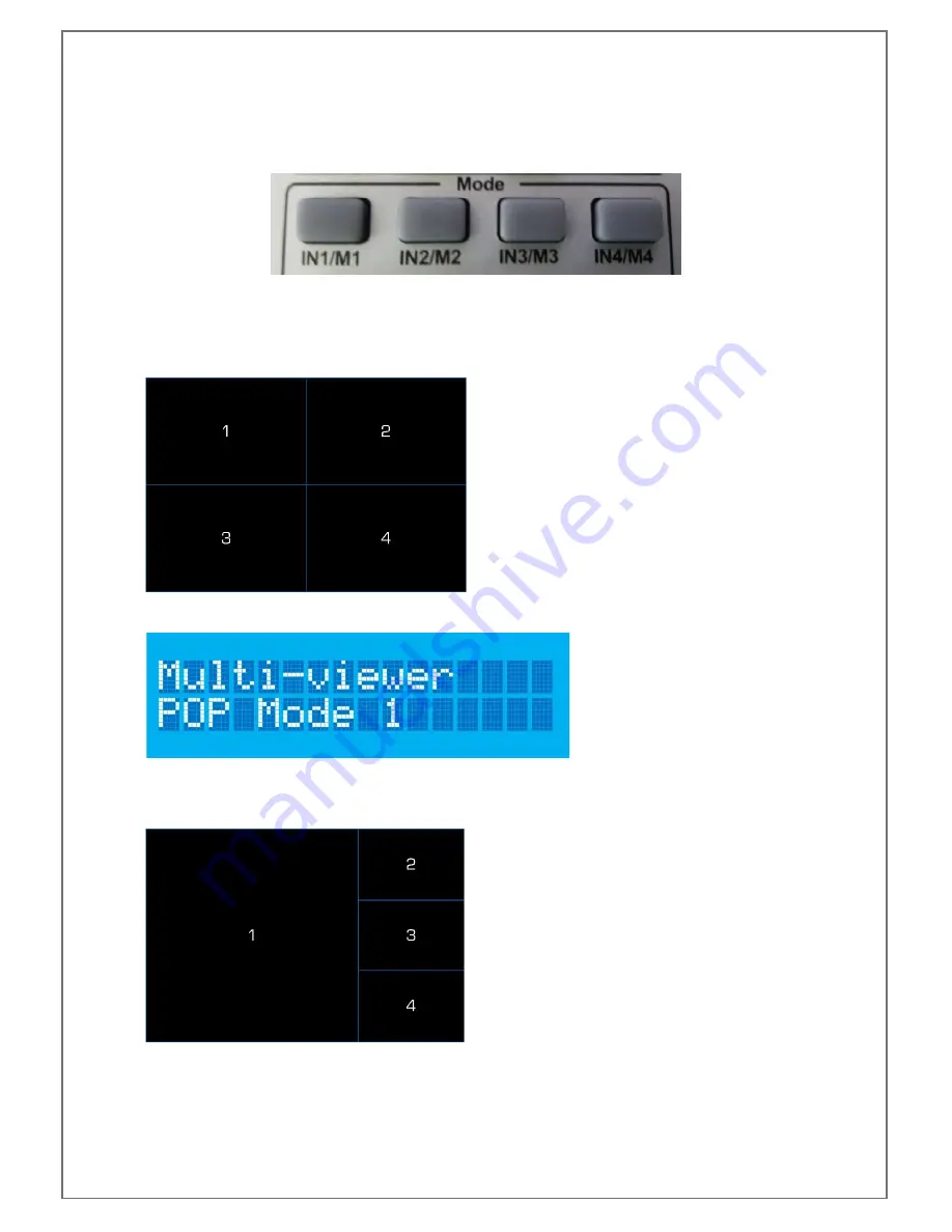
Four buttons are available in the Mode section of the handset, M1, M2, M3 and M4. When in PIP/POP or as 
it is denoted on the LCD panel Multi-viewer mode, any of the four buttons can be pressed to change between 
the four layouts of the PIP/POP mode. 

Pressing M1, the image layout will be set to: 


The LCD will display: 


Pressing M2, the image layout will be set to: 


Summary of Contents for Sds-2500

Page 1: ......

Page 2: ...hich may cause or be susceptible to radio interference Users may need to take additional measures to mitigate the interference This is an RF Radio product which may cause or be susceptible to radio in...

Page 3: ...ystem Switch off and disconnect the equipment from all power sources prior to handling installation or wiring otherwise it may cause electric shock or equipment damage This product grounds to earth by...

Page 4: ...A SWITCH 11 5 2 2 TCP IP CONNECTION DIRECT VIA CROSS CONNECT 11 6 INITIAL SETUP 12 6 1 INSTALLATION 12 6 2 SIGNAL CONNECTIONS 13 7 FRONT PANEL OPERATION 14 7 1 SYSTEM CONTROLS 14 7 1 1 POWER 14 7 1 2...

Page 5: ...CP IP for interfacing to an external control system The SDS 2500 has comprehensive EDID management allowing users to assign a number of EDID values from 480i to 1080p to any of the four inputs EDID co...

Page 6: ...eiver Accept commands from supplied infra red handset b Power Button Place or remove system from standby with LED indicator c Lock Button Front panel control lock with LED indicator 3 INPUT AND OUTPUT...

Page 7: ...RED CONNECTORS 2 ANALOGUE VIDEO INPUTS 4x HD15 for RGBHV 4x Single Phono for composite video and 4x 3 5mm stereo jacks for stereo audio 3 REMOTE CONTROL INTERFACE 1x D9 for RS232 and 1x RJ45 for TCP I...

Page 8: ...SDS 2500 USER MANUAL V1 0 2018 Smart e UK Ltd www smart e co uk PAGE 8 4 APPLICATION DIAGRAM 4 1 4X4 MATRIX APPLICATION...

Page 9: ...SDS 2500 USER MANUAL V1 0 2018 Smart e UK Ltd www smart e co uk PAGE 9 4 2 2X2 VIDEO WALL APPLICATION...

Page 10: ...SDS 2500 USER MANUAL V1 0 2018 Smart e UK Ltd www smart e co uk PAGE 10 4 3 QUAD SPLIT POP PIP APPLICATION...

Page 11: ...Linear Order PIN 1 PIN 2 PIN 3 PIN 4 PIN 5 PIN 6 PIN 7 PIN 8 White Orange Orange White Green Blue White Blue Green White Brown Brown 5 2 2 TCP IP CONNECTION DIRECT VIA CROSS CONNECT Utilise a cross c...

Page 12: ...available the first of which is for the SDS 2500 to be mounted in a 19 rack mounting solution 2x rack mounting ears are provided in the packaging for the SDS 2500 along with 6x counter sunk screws Usi...

Page 13: ...er to section 3 of this manual Firstly connect all of the video inputs and outputs required It is ok to connect multiple mixed format inputs to the unit at the same time for instance you could connect...

Page 14: ...hown below 7 FRONT PANEL OPERATION 7 1 SYSTEM CONTROLS 7 1 1 POWER When the system is on the power LED will be lit green To place the unit in standby press and hold the power button for 3 seconds the...

Page 15: ...ge in settings Press and release the lock button the lock LED will light red The LCD will show the panel lock notification for 5 seconds before returning to its previous state 5 seconds To unlock the...

Page 16: ...ill then update to show as below This screen will be displayed for five seconds within this time you must press the Enter button located in the EDID section of the front panel If pressed within five s...

Page 17: ...the four inputs of the SDS 2500 the input button which has been pressed will be reflected on the screen as that number will be flashing This screen will be displayed for five seconds with no further i...

Page 18: ...initiate a crosspoint change press one of the output buttons As an example we will change output B to input 3 Firstly press Output B button B will flash on the LCD to show that output is now being con...

Page 19: ...will update to show one of the three EDID options as shown below the options can be navigated through using the UP and DOWN buttons Once the desired EDID is seen on the LCD display press the ENTER ke...

Page 20: ...e the correct input s is shown on the LCD press the ENTER button the screen will briefly show a holding screen Before updating to show the EDID has been read correctly For more detailed EDID settings...

Page 21: ...e infra red receiver on the front of the unit 8 1 MODE SELECTION Three buttons are available on the handset to switch between the different modes of the SDS 2500 These buttons are located in the Mode...

Page 22: ...3 button The LCD display will update to show the input video format selection screen with number 3 flashing to indicate this is the input being controlled The input will flash for 5 seconds within th...

Page 23: ...nt If we start with the example of all outputs set to input 1 If you wish to for example change output D to input4 first press the Output D button The D icon on the LCD will flash to show it is the se...

Page 24: ...7 2 and 8 1 of this manual Four buttons are available in the Mode section of the handset M1 M2 M3 and M4 When in PIP POP or as it is denoted on the LCD panel Multi viewer mode any of the four buttons...

Page 25: ...DS 2500 USER MANUAL V1 0 2018 Smart e UK Ltd www smart e co uk PAGE 25 The LCD will display Pressing M3 the image layout will be set to The LCD will display Pressing M4 the image layout will be set to...

Page 26: ...ny of the four buttons can be pressed to change the input being displayed on the video wall output The SDS 2500 can only display a 2x2 video wall so any input selected will be displayed as a singled i...

Page 27: ...e ensure the adapter used is compatible with your PC or laptop A PC application HDMI 944F is made available from the Smart e website This gives a greater degree of control for advanced users A separat...

Page 28: ...e rear of the unit to accept control via TCP IP communications To set up TCP IP communications you will need to connect the SDS 2500 to your network or PC using the appropriate cabling Then refer to s...

Page 29: ...provided handset for the SDS 2500 This allows for the SDS 2500 to be installed in a concealed location whilst still having infra red control by running a infra red receiver to a location visible to th...

Page 30: ...creen being observed For the example below output 3 is displaying the video from the blu ray player connected to input 1 Infra red will be directed from the IR receiver at the screen connected to outp...

Page 31: ...UK Ltd www smart e co uk PAGE 31 If output 3 is then switched to display video from input 2 the infra red will be directed to control the SD DIGIBOX Once again the red path as below shows the directi...

Page 32: ...face 2 TX 3 RX 5 GND Ethernet control Ethernet control interface RJ 45 female interface Ethernet control protocol TCP IP Ethernet control rate Adaptive 10M 100M full duplex or half duplex Specificatio...

Page 33: ...5ns 1ns Signal Strength T M D S 0 4V p p Minimum Maximum Level T M D S 2 9V 3 3V Impedance 50 EDID Optional default EDID and load function Maximum DC Offset error 15mV Maximum Input cable length 15 me...

Page 34: ...connectors Signal types PAL NTSC3 58 NTSC 4 43 SECAM PAL M PAL N Gain 0dB Bandwidth 150 MHz 3dB Differential Phase Error 0 1 3 58 4 43 MHz Differential Gain Error 0 1 3 58 4 43 MHz Signal Strength 1V...

Reviews: