40
Connection of Electrical Components
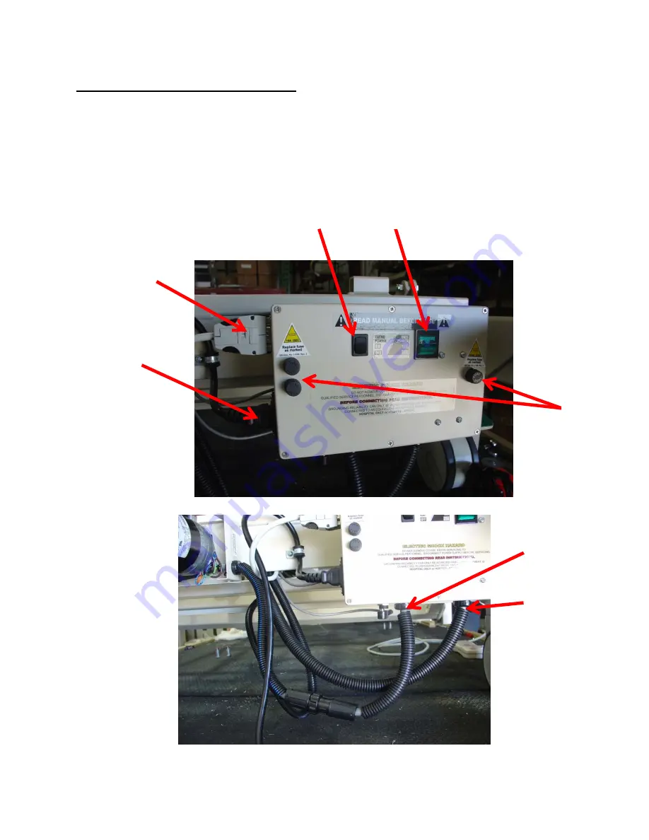
Should it become necessary to remove any of the cables from the control box, the diagram below
will assist in finding the appropriate cables.
The diagram also indicates the fuse placement. If needed, replace fuses as marked.
A.
Main Power
B.
Hand Control
C.
Trendelenburg ON/OFF
D.
Main Unit Power
E.
Fuses
F.
Head Deck/Articulation
G.
Foot Deck/Articulation
B
A
C
D
E
F
G


