5
•
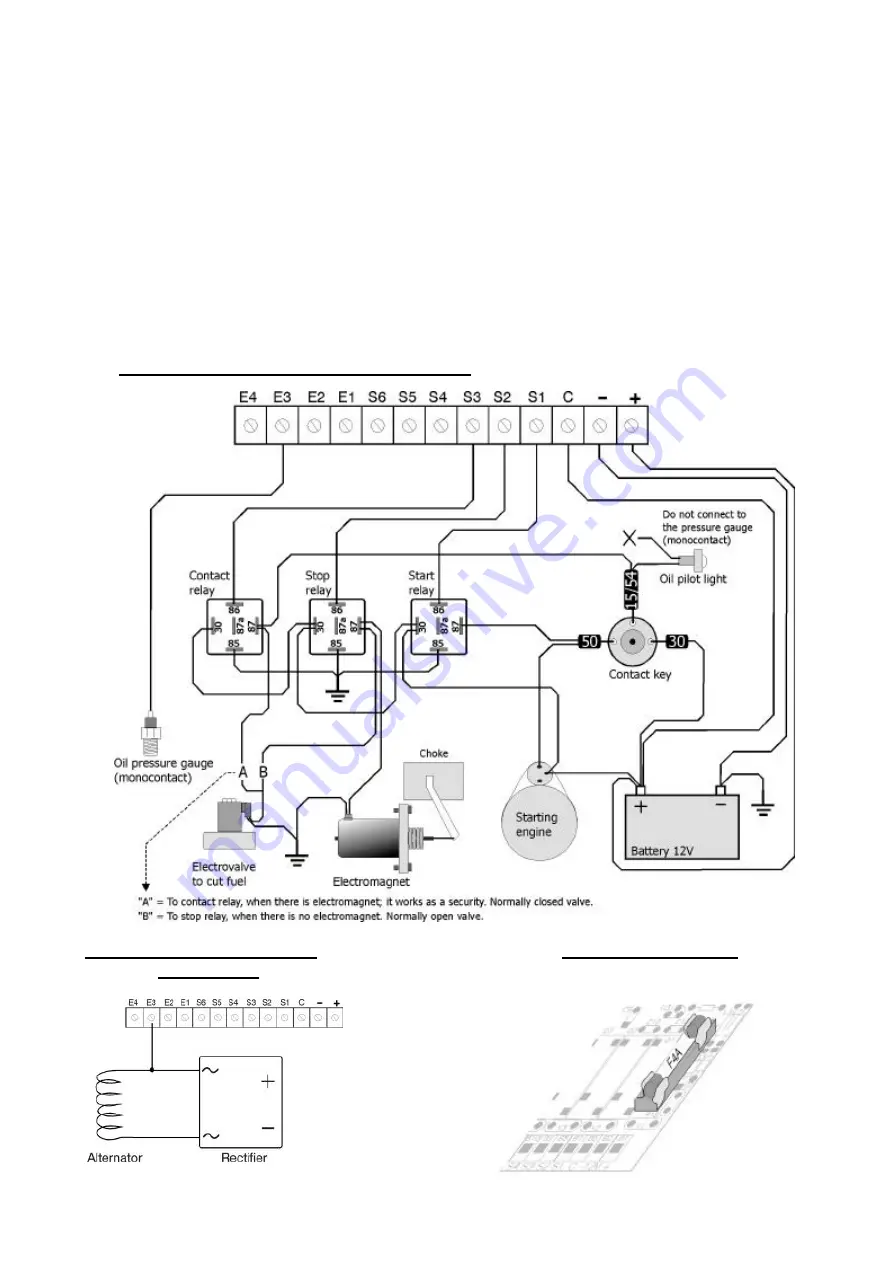
Outlet 1: Engine start. A supplementary relay, with
a capacity between 20 and 30 Amps, must be
inserted, connecting its outlet to the terminal cable
“50” of the key.
•
Outlet 2: Engine stop. If the stop is done by
electromagnet, a supplementary relay is to be
inserted between the electromagnet and outlet 2.
If the stop is done by cutting the fuel with an
electrovalve, this valve is to be installed by the
injector, so that the stop takes place as soon as
possible.
When the electrovalve is normally open, it is
connected directly to output 2. If the electrovalve
is normally closed, it will be connected to outlet 3.
With the electrovalve normally open, this one is
closed during the final time of the working. If the
electrovalve is normally closed, this one is opened
at the beginning of the working and closed at the
end.
•
Outlet 3: Diesel engine ignition. It is to be
connected to the terminal cable “15/54” of the
key. The unit starts and stops itself, so the key has
to be left at rest.
•
Outlets 4, 5 and 6: Their function will depend on
what is configured according to table number 1.
Figure 4. Unit connection with a diesel engine
Figure 5. Unit connection to a
Figure 6. Fuse location
petrol engine


