AIR-TO-WATER HEAT PUMP INSTALLATION MANUAL
Error
indicating lamp
Running
indicating lamp
XT
2
Ins
ide
U
ni
t
El
ec
tr
ic
B
ox
L1
N
XT
1
Water tank
LK
POW
E
R
3
80
4
15
V-
3P
h-
50
H
z
Disp
la
y
bo
ar
d
CN
16
CN
5
AP
2-
wa
y
val
ve
1
2-w
ay
val
ve
2
3-
wa
y
va
lv
e1
3-w
ay
va
lv
e2
Wat
er-
tank
tem
p sens
or2
Wa
ter-
tank
te
mp
se
nsor1
O
u
td
oor
Un
it
PE
Ma
in
B
ao
rd
CN
14
R
emo
te
a
ir
te
m
p s
ensor
Lo
ng
-d
is
ta
nce
mo
ni
to
r P
C
CN7
Oth
er
the
rm
al sy
stem
Water- ou
t te
mp
sen
sor
PE
Th
er
mo
st
at
T
her
mo
st
at
P
o
w
e
r
su
p
p
ly
f
o
r T
h
e
rm
o
st
a
t:If
it
is
230V
A
C
,pl
eas
e
co
n
n
e
ct
T
e
rm
in
a
l b
lo
ck
(x
t3
)
2
1
.2
2.23
.24
;If
it
is
2
4V
A
C
, p
le
a
se
c
o
n
n
e
ct
T
e
rm
in
a
l bl
oc
k(
xt3
)
25.
26.
27.
28.
T
h
e
y a
re
c
a
n
n
o
t b
e
c
o
n
n
e
cte
d
as
the
sam
e
tim
e.
If
t
he
re
is
g
at
e
co
nt
ro
l f
un
ct
io
n,
pul
l
ou
t
th
e
lea
di
ng
w
ir
e
50
on
te
rm
in
al
b
oar
d
XT
2)b
et
we
en
19
a
nd
2
0
an
d
th
en
co
nn
ec
t
th
e
G
ate
-c
on
tr
ol
le
r
G
a
te
-c
o
n
tr
oller
20
19
S
pe
cif
ic
ation:
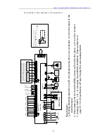
1
Running indicating lam
p(HL1) and Error
indicating lam
p (HL2) are
co
nnec
te
d or not on the basis of the
c
lient
s'demand.
2
Client water pump A
C co
n
ta
ct
or
(K
M
4)
is
b
a
ck
-u
p
P
um
p
fo
r the future , so it is not be connect;
3L
ea
ka
g
e S
w
itc
h
(
LK
)
is necess
ary for additional in
st
al
lat
ion, Please reference to
pa
ge
3
7 17
.4
.2
S
p
ec
ifi
cat
io
n
of
P
ow
er
S
upply
Wire
and Leakage Switch.
L2
L3
L1
L2
L3
N
29
30
31
XT
2
BK
B
N
BU
YE
G
N
PE
GSH-12IRA/ERA-3,GSH-140IRA/ERA-3, GSH-160IRA/ERA-3
49
Summary of Contents for GSH-100ERA series
Page 2: ......
Page 49: ...AIR TO WATER HEAT PUMP INSTALLATION MANUAL GSH 120ERA 3 GSH 140ERA 3 GSH 160ERA 3 47 ...
Page 62: ......
Page 63: ......


