AIR-TO-WATER HEAT PUMP INSTALLATION MANUAL
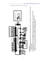
silk screen
location
specification
AC-L -
live wire of power supply
N -
Neutral wire of power supply
PUMP1 X13
live wire of indoor water pump
PUMP2 X14
live wire of solar water pump
RUN X15
running indicator
HEAT3-L X16
e-heater of water tank
HEAT1-L X17
e-heater of indoor unit 1
HEAT2-L X18
e-heater of indoor unit 2
ERR X19
error indicator
2V1_OFF X5
Electric magnetic 2-way valve1 is normally closed.
2V1_ON X6
Electric magnetic 2-way valve1 is normally open.
2V2_OFF X7
Electric magnetic 2-way valve2 is normally closed.
2V2_ON X8
Electric magnetic 2-way valve2 is normally open.
3V1_OFF X9
Electric magnetic 3-way valve1 is normally closed.
3V1_ON X10
Electric magnetic 3-way valve1 is normally open.
3V2_OFF X11
Electric magnetic 3-way valve2 is normally closed.
3V2_ON X12
Electric magnetic 3-way valve2 is normally open.
T-SENSOR1 CN10
terminal of temperature sensor1
T-SENSOR2 CN11
terminal of temperature sensor2
T-SENSOR3 CN12
terminal of temperature sensor3
T-SENSOR4 CN13
terminal of temperature sensor4
T-SENSOR5 CN14
terminal of temperature sensor5
T-SENSOR6 CN15
terminal of temperature sensor6
DOOR-C CN23
Door detection input
OVC-HEAT3 CN28
e-heater of water tank adhesion-proof protection detector
OVC-HEAT1 CN26
e-heater of indoor unit1 adhesion-proof protection detector
OVC-HEAT2 CN27
e-heater of indoor unit2 adhesion-proof protection detector
IN-SW CN25
detection input of water flow switch
COM-MANUAL CN6
connect the wired controller
COM-OUT CN5
connect to outdoor unit
COM-BMS CN7
connect to remote controller
TR-OUT1 CN2
transformer output 1
TR-OUT2 CN3
transformer output 2
TR-IN CN1
220V in put of transformer
CN30 CN30
heavy-current interface of end controller
CN31 CN31
heavy-current interface of end controller
18.2 ELECTRIC WIRING WORK
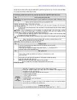
18.2.1 Wiring Principle
①
General principles
Wires, equipment and connectors supplied for use on the site must be in compliance with
provisions of regulations and engineering requirements.
Only electricians holding qualification are allowed to perform wire connection on the site.
Before connection work is started, the power supply must be shut off.
Installer shall be responsible for any damage due to incorrect connection of the external
circuit of the unit.
Caution --- MUST use copper wires.
②
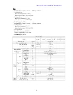
Connection of power cable to the electric cabinet of the unit
Power cables should be laid out through cabling trough, conduit tube or cable channel.
Power cables to be connected into the electric cabinet must be protected with rubber or
plastic to prevent scratch by edge of metal plate.
Power cables close to the electric cabinet of the unit must be fixed reliably to make the
power terminal in the cabinet free from an external force.
Power cable must be grounded reliably.
44
Summary of Contents for GSH-100ERA series
Page 2: ......
Page 49: ...AIR TO WATER HEAT PUMP INSTALLATION MANUAL GSH 120ERA 3 GSH 140ERA 3 GSH 160ERA 3 47 ...
Page 62: ......
Page 63: ......


