background image


21


Step 2.  Program Device Types and Point Types for FACP Control Points.

  Use the 

FACP programmer to accomplish the following steps: 
 

a.  Add the XALIC Card to the job.  See the corresponding chapter in the 

ES Panel 

Programmer’s Manual

 (574-849) for information on doing this. 


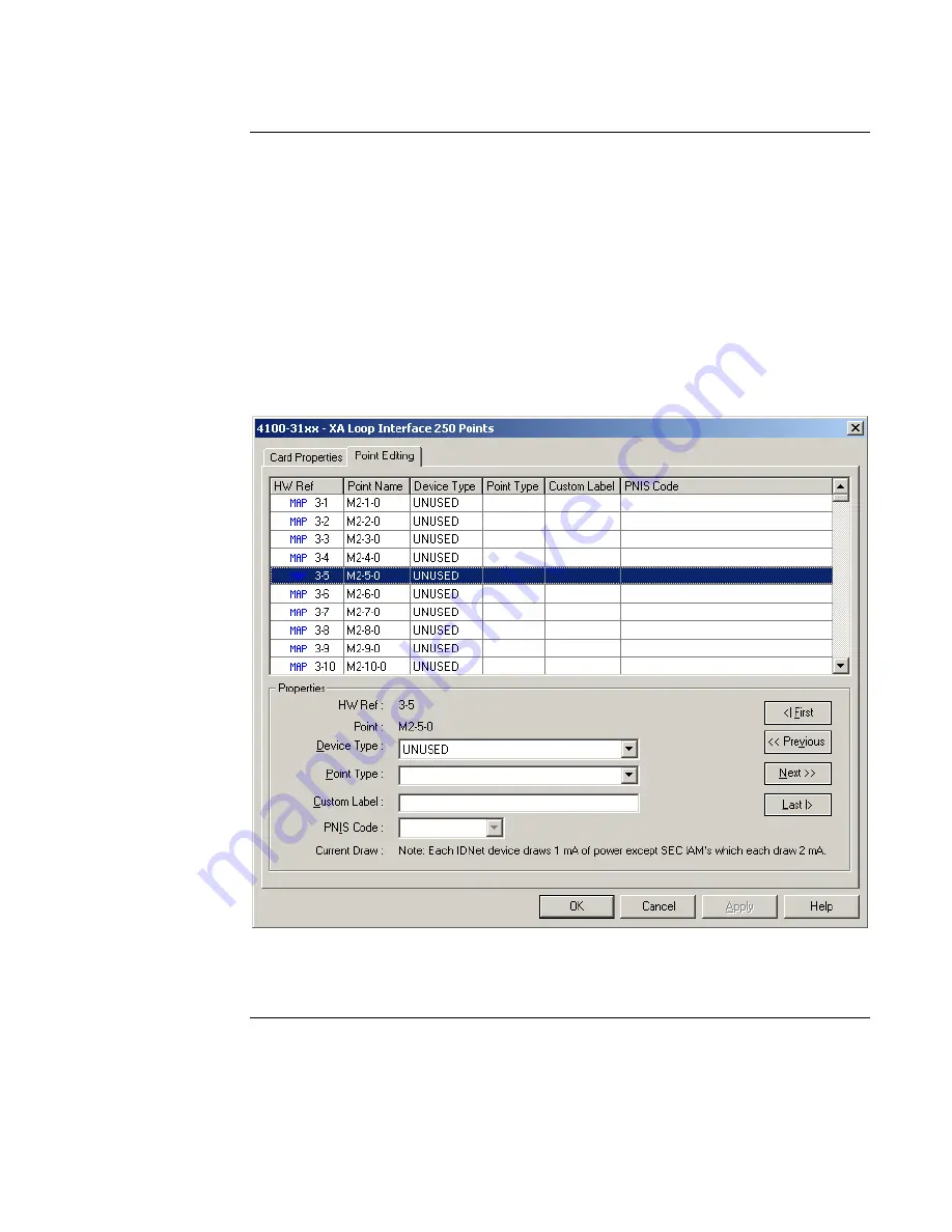
b.  Click on the Hardware Tab.  Expand the Unit/Box/Bay icons containing the XALIC card.  

Double click on the XALIC card icon and choose the Point Editing tab, as shown in the 
screen example below. 
 

c.  Examine the Point Name field and identify the name of the point you want to edit.  

Before the Device Type is programmed, the  Point Name will have a 0 in the subpoint 
field. (M2-5-0, for example).  Remember that the number in the middle, 5 in this case, 
corresponds to the similarly numbered XA Device on the Autocall side. 


Figure 16.  XA Loop Point Editing 

d.  Click on the Device Type drop down list box and select 

MLPTIO

.  After you make your 

selection, the screen updates to display the subpoints.  See Figure 17. 
 

Continued on next page 

Programming FACP as an XA Loop Slave, 

Continued 

Programming 
Control Points


firealarmresources.com

Summary of Contents for 4100-3115 XALIC

Page 1: ...rface Card XALIC This card allows a 4100U or a 4100ES Fire Alarm Control Panel FACP to function as either the XA Loop Master or as an XA Loop Slave This card is compatible with a 4100U FACP or a 4100E...

Page 2: ...nd to comply with the limits for a Class A digital device pursuant to Part 15 of the FCC Rules These limits are designed to provide reasonable protection against harmful interference when the equipmen...

Page 3: ...nnects the XALIC to the XA loop 18 position terminal block consists of two separate sets of terminals one for master operation and one for slave operation P4 PDI Connector a 10 pin connector located o...

Page 4: ...F SIG CMD CLK MASTER SLAVE CLASS A CLASS B RUI RUI SHLD AUX AUX JUMPERS RIGHT FOR SIGNAL POWER JUMPERS LEFT FOR AUX POWER SW1 SW2 TB3 XA Loop Field Wiring Terminal Block TB3 Baud Address Dip Switch SW...

Page 5: ...a power supply that is UL listed for fire protective signaling use XA Loop Max Resistance 100 per wire Max Capacitance 1 5 f wire to wire 1 5 f wire to shield Normal Supervision Current 500 mA Maximu...

Page 6: ...switch to ON SW2 2 through SW2 8 These switches set the card address Refer to Table 3 for a complete list of the switch settings for all of the possible card addresses Note You must set these switches...

Page 7: ...ON OFF OFF OFF 28 ON ON OFF OFF OFF ON ON 88 OFF ON OFF OFF ON ON ON 29 ON ON OFF OFF OFF ON OFF 89 OFF ON OFF OFF ON ON OFF 30 ON ON OFF OFF OFF OFF ON 90 OFF ON OFF OFF ON OFF ON 31 ON ON OFF OFF OF...

Page 8: ...he 257 pulse setting 1 2 3 4 On Off Figure 3 Location of SW1 Jumpers P1 and P2 select the power and ground source for the XALIC Set these jumpers as follows depending on whether you are connecting AUX...

Page 9: ...t if the XALIC is being configured as an XA Loop Slave To enable Earth Detect place the jumper in positions 1 2 To disable Earth Detect place the jumper in positions 2 3 P3 Install Jumper on pins 1 an...

Page 10: ...ide of the XALIC card to connect to one of the PDI connectors on the lower row as shown in the figure below Secure the card to the Expansion Chassis using the supplied hardware Note Jumper P1 and Jump...

Page 11: ...t in an expansion chassis Secure the card to the backbox using the hardware supplied with the card Place Jumpers P1 and P2 in the leftmost position and connect the XALIC to the Aux power source as sho...

Page 12: ...om the CLK B CMD B SIG B REF B and SHLD outputs of the XALIC card to the appropriate inputs on a XA Loop device 2 Route wire from the first XA Loop device to the next one Repeat for each appliance 3 R...

Page 13: ...MD A to CMD B and CLK A to CLK B If the jumper is absent a XA Loop Wiring fault will be indicated 2 Route wire from the CLK B CMD B SIG B REF B and SHLD outputs of the XALIC card to the appropriate in...

Page 14: ...o 18 AWG 0 8231 mm2 To connect the XA Loop Interface Card XALIC as a Slave on the XA Loop do the following 1 Route CLK CMD SIG REF and SHLD from the previous XA Device XA Master to TB3 on the XALIC ca...

Page 15: ...addresses occupied by XA loop devices 1 2 4 or 8 pt input output output only or input only is limited to 200 based upon current limitations There is no address limitation for Data Gathering Panels DG...

Page 16: ...ce type to an address within the range 1 through 245 when the corresponding XA device is an output only device XA output only devices must be at address 245 or below MLPTIO Assign this device type to...

Page 17: ...ype to the address the state of the XALIC address is either ON or OFF Follow these steps to program XALIC points 1 Add the XALIC Card to the job See the corresponding chapter in the ES Panel Programme...

Page 18: ...only device click on the subpoint and then click on the Point Type drop down list box and choose the output point type Refer to 574 849 for point type definitions Points 246 255 Devices in this addre...

Page 19: ...put for XA Device 249 248 Subpoint 1 is the input and subpoint 5 is the output for XA Device 250 248 Subpoint 2 is the input and subpoint 6 is the output for XA Device 251 249 Subpoint 1 is the input...

Page 20: ...stom control equations execute Each FACP XALIC Control Point address consists of three parts the MAPNET channel number the XA Loop Device Number and the Subpoint The MAPNET channel number is automatic...

Page 21: ...reen example below c Examine the Point Name field and identify the name of the point you want to edit Before the Device Type is programmed the Point Name will have a 0 in the subpoint field M2 5 0 for...

Page 22: ...or the point g Click Apply to save the changes Step 3 Write Custom Control The control point functions as an on off switch for one or more FACP Custom Control equations Typical equations include the f...

Page 23: ...e of the XALIC status points For any given XALIC status point subpoint 5 is always the fire point and subpoint 6 is always the trouble point This triggers the corresponding XA device at the Autocall h...

Page 24: ...ing tab as shown in the screen example below c Examine the Point Name field and identify the name of the point you want to edit Before the Device Type is programmed the Point Name will have a 0 in the...

Page 25: ...e list enters an alarm state the OUT side of the equation executes turning on M2 1 5 and its corresponding XA device on the Autocall head end Some programming on the Autocall head end would then be re...

Page 26: ...feteria L512 M5 1 Area 2 Gymnasium L513 M5 2 Area 3 Auditorium L514 M5 3 Area 4 Laboratory L515 M5 4 It is also necessary to annunciate any other Panel trouble to the Autocall panel and we will do tha...

Page 27: ...tom Control equations to activate those outputs under the proper circumstances so both subpoint 5 and 6 on XALIC devices 1 5 should be programmed with the RELAY point type The Custom Control equations...

Page 28: ...202 ON PRI 9 9 System Reset pseudo point END The Autocall panel will be programmed to activate command receiver addresses 8 11 whenever a corresponding switch is activated in the panel This will cause...

Page 29: ...PS containing one IDNet channel by default M1 and an XA Loop Interface Card XALIC M2 Since this a master configuration the TRIAM device type is used for the smoke detectors and pull stations and the R...

Page 30: ...firealarmresources com...

Page 31: ...firealarmresources com...

Page 32: ...579 513 Rev D firealarmresources com...

Reviews: