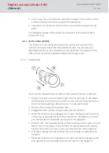
2. Then screw the core extraction protection adapter into position on the
cylinder and lock into place using the threaded pins.
3. Install the non-electronic knob on the core extraction protection ad-
apter.
An elongated version of the adapter is available for the Italian market.
(Z4.KA.SET2.IT).
6.3.4 Half Cylinder DK/MR
The thumb-turn, including the inside tube, can be removed from the
cylinder housing to install the DK and MR versions. The procedure is
described below. It is only necessary for key switches, for example, if the
half cylinder cannot be installed using the fastening screw.
6.3.4.1 Disassembly
If you need to disassemble the half cylinder, please proceed as follows:
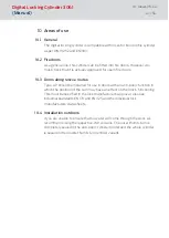
1. Using a tool such as a screwdriver, grip into the two slots in the plastic
disc between the thumb-turn and the profile cylinder housing and turn
the tool while applying a little pressure. This breaks the disc.
2. Remove the remains of the plastic disc.
3. Engage the half cylinder using an authorised ID medium.
4. While the thumb-turn is engaged, turn it anti-clockwise until it will turn
no more (e.g. towards the lock when installed or holding the cam with
your hand when not installed; see Step A in the diagram).
5. Press thumb-turn towards profile cylinder housing until it stops (you will
hear it click. If necessary, move thumb-turn backwards and forwards
several times until you hear a click; see Step B and D in the diagram).
6. If needed, engage the half cylinder once more using an authorised ID
medium.
7. While the thumb-turn is engaged, turn it anti-clockwise and apply pres-
sure against the stop position (see Step B and D in the diagram).
Digital Locking Cylinder 3061
(Manual)
6. Installation instructions
31 / 54


