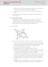
8. While applying pressure, pull the thumb-turn (including inside tube)
from the profile cylinder (see Step D in the diagram).
NOTE
You must not strike the thumb-turn during installation. Do not allow the
cylinder to come into contact with oil, paint or acids.
6.3.4.2 Installation
1. Remove the metal discs on the inside tube and push a plastic disc onto
it instead. You will find the plastic disc in the supplied package.
2. Push the removed metal discs onto the inside tube, so that a plastic
disc and a varying number of metal discs, depending on the half cylinder
type, are on the inner tube.
3. Push the inner tube thumb-turn into the profile cylinder housing until it
stops.
4. Engage cylinder using an authorised ID medium.
5. While the thumb-turn is engaged, press it gently against the profile cyl-
inder housing while turning clockwise at the same time until the inside
tube clicks into place in the profile cylinder housing.
NOTE
Check that it has locked into position correctly by pulling the thumb-turn
gently while turning it backwards and forwards.
NOTE
You will find the required plastic discs in the supplied package.
When installing, ensure that only one plastic disc and the same number of
metal discs are on the inner tube as when you took it apart. The plastic disc
must be placed directly on the thumb-turn.
6.3.4.3 Functions test
1. Engage half cylinder using a valid ID medium and turn the thumb-turn in
the locking and opening direction with the door open. The thumb-turn
must be able to rotate easily when you do so.
2. Close the door and repeat the process. If the half cylinder should be
stiff, you need to align the door or modify the strike plate.
Digital Locking Cylinder 3061
(Manual)
6. Installation instructions
32 / 54


