background image

Air Hose Reel

317338

7

silverlinetools.com

e)  Select, maintain and replace the consumable/inserted tool as recommended in the 

instruction handbook, to prevent an unnecessary increase in dust or fumes.

f)  Use respiratory protection in accordance with employer’s instructions and as required by 

occupational health and safety regulations.

Specific Safety 

Additional Safety Instructions for Pneumatic Devices

Air under pressure can cause severe injury:
•  Always shut off air supply, drain hose of air pressure and disconnect device from air supply when 

not in use, before changing accessories or when making repairs

•  Never direct air at yourself or anyone else
•  Whipping hoses can cause severe injury. Always check for damaged or loose hoses and fittings
•  Whenever universal twist couplings (claw couplings) are used, lock pins should be installed and 

whip check safety cables should be used to safeguard against possible hose-to-tool or hose-to-

hose connection failure

•  Do not exceed the maximum air pressure stated on the device
•  Never carry an air tool by the hose 
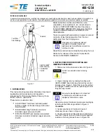
1. Air Inlet Hose
2. Rubber Stop
3. Male EU Quick Connector
4. Female EU Quick Connector
5. Rubber Protector
6. Air Outlet Hose
7. Sleeve Anchor Bolt (M8 x 40mm, 10mm OD)
8. Bracket Securing Clip
9. Bracket Release Button

10. Wall/Ceiling Mounting Bracket
11. Bracket Fixing Hole
12. Hose Reel Housing
13. Reel Tensioning Axle
14. Securing Clip Release
15. Spring Tension Safety Pin

Product Familiarisation

Intended Use 

Garage or workshop retractable 9m air hose reel with multi-position mounting bracket for fixing to 

wall or ceiling. For use with compatible air tools.  

Unpacking Your Product 

•  Carefully unpack and inspect your product. Fully familiarise yourself with all its features and 

functions

•  Ensure all parts of the product are present and in good condition. If any parts are missing or 

damaged, have such parts replaced before attempting to use this product 

Before Use 

WARNING

: Always disconnect the hose from the compressed air supply before carrying out any 

maintenance or repair work on this device.

WARNING

: Release the spring tension before disassembling the Hose Reel Housing (12).

WARNING

: DO NOT remove any safety device fitted to this device.  
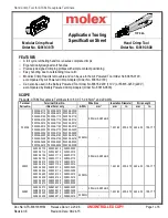
Assembly

Mounting the bracket:

•  The Mounting Bracket (10) can be ceiling or wall mounted (Fig. I)
1.  Remove the Reel Housing (12) from the Bracket by lifting the Securing Clip Release (14) and 

sliding the Bracket Securing Clips (8) (Fig. II). Then press the Bracket Release Buttons (9) and 

slide the Bracket off the Hose Reel Housing (Fig. III)

2.  Select whether the Bracket is to be wall or ceiling mounted
3.  Position the Bracket where it is to be mounted
4.  Using the Fixing Holes (11) as a template (Fig. IV), use a pencil or marking chalk (not supplied) to 

mark the hole positions for the Sleeve Anchor Bolts (7)

5.  Remove the Bracket from the mounting position and drill the 2 x 10mm holes using a 10mm 

drill bit (not supplied), to a minimum depth of 40mm (Fig. V)

WARNING

: Always use a detector to check for hidden power cables or pipework before drilling.

Note

: When drilling, ensure that the correct type of drill bit is used for the material being drilled.

6.  Insert the Sleeve Anchor Bolts into the holes (Fig. VI)

Note

: The Bolts may require tapping into the hole using a hammer (not supplied). Do not increase 

the diameter of the hole to incorporate the Bolts.
7.  Unscrew and remove the Bolt and washers from the inserted Sleeve (Fig. VII)
8.  Position the Bracket and attach to the wall or ceiling using the Sleeve Anchor Bolts 
9.  Attach the Hose Reel Housing to the Bracket in reverse order to removal and ensure the Securing 

Clips (8) are in the locked position (Fig. VIII)

Adjusting the hose length

•  The Rubber Stop (2) should only be adjusted moving inwards towards the Reel Housing and 

should not be moved outwards towards the end of the Outlet Hose (6) (Fig. IX)

•  For each metre the Rubber Stop is moved inwards, the spring tension must be reduced by one 

full rotation (see ‘Adjusting the spring tension)

•  To reduce the length of the Outlet Hose, adjust the Rubber Stop then cut the Hose to the required 

length

•  Ensure the length of the Hose outwards of the Rubber Stop is between 0.1-1.99m  

(Fig. X) 

Operation 

Extending the Hose

•  Pull out the Hose to the required length and slowly retract to lock it in position (Fig. XI)

Retracting the Hose

WARNING

:  DO NOT let go of the Hose while it is being retracted as this may cause personal 

injury and damage the Hose Reel.
•  To retract the Hose, pull the Hose to unlatch the locking mechanism then allow the Hose to 

retract into the Housing (Fig. XII) 

Accessories 

•  A full range of accessories including air hose connectors is available from your Silverline stockist
•  Spare parts can be obtained from toolsparesonline.com 

317338_Manual.indd   7

11/12/2017   12:11

Summary of Contents for 317338

Page 1: ...GARANTIE A OSDEGARANT A ANNIDIGARANZIA JAARGARANTIE LATAGWARANCJI XXXXXX 317338 FR Enrouleurdetuyaupneumatique DE Druckluftschlauchtrommel ES Carreteconmangueraneum tica IT Avvolgituboautomaticopertub...

Page 2: ...2 12 1 2 4 5 6 7 3 11 10 14 8 9 15 13 317338_Manual indd 2 11 12 2017 12 11...

Page 3: ...silverlinetools com 3 10mm 10mm Fig I Fig III Fig V Fig VI Fig VII Fig IV Fig II 317338_Manual indd 3 11 12 2017 12 11...

Page 4: ...4 Fig VIII Fig IX Fig XI Fig XIII Fig XIV Fig XV Fig XII Fig X 317338_Manual indd 4 11 12 2017 12 11...

Page 5: ...silverlinetools com 5 English 6 Fran ais 10 Deutsch 14 Espa ol 18 Italiano 22 Nederlands 26 Polski 30 317338_Manual indd 5 11 12 2017 12 11...

Page 6: ...een given supervision or instruction concerning use of the device by a person responsible for their safety Children must be supervised to ensure that they do not play with the device Projectile Hazard...

Page 7: ...wall mounted Fig I 1 Remove the Reel Housing 12 from the Bracket by lifting the Securing Clip Release 14 and sliding the Bracket Securing Clips 8 Fig II Then press the Bracket Release Buttons 9 and sl...

Page 8: ...rechecking the tension 5 When the desired tension is achieved align the hole in the Axle with the Reel Housing and insert the Spring Tension Safety Pin Fig XV 6 The spanner can now safely be removed 7...

Page 9: ...ect unsuitable or unsafe deliveries All work will be carried out by Silverline Tools or its authorized repair agents The repair or replacement of the product will not extend the period of guarantee De...

Page 10: ...norme ISO 11148 sont bien lisibles Il est de la responsabilit de l employeur l utilisateur de contacter le fabricant pour obtenir une plaque signal tique de remplacement si n cessaire AVERTISSEMENT C...

Page 11: ...D branchez toujours le tuyau de la source d air comprim avant d effectuer tout travail d entretien ou de r paration sur ce produit AVERTISSEMENT Neutralisez la tension du ressort avant de d sassemble...

Page 12: ...rque NE PAS faire tourner l axe plus d un tour complet sans rev rifier la tension 5 Une fois la tension voulue tablie alignez le trou de l axe avec le d vidoir et r introduisez la goupille de s curit...

Page 13: ...r paration agr s La r paration ou le remplacement du produit ne d passera pas la p riode de garantie Les anomalies que nous reconnaissons tre couvertes par la garantie seront rectifi es par la r parat...

Page 14: ...der Schlauchtrommel sowie die bei dessen Verwendung auftretenden Kr fte handhaben zu k nnen d Halten Sie die Schlauchtrommel vorschriftsm ig Seien Sie jederzeit bereit pl tzliches Ausschlagen abzufang...

Page 15: ...sprechend kompatiblen Druckluftwerkzeugen Auspacken des Ger tes Packen Sie Ihren Artikel vorsichtig aus und berpr fen Sie ihn Machen Sie sich vollst ndig mit allen seinen Eigenschaften und Funktionen...

Page 16: ...eparaturen m ssen unter Verwendung von Original Ersatzteilen von einer zugelassenen Silverline Vertragswerkstatt ausgef hrt werden Federspannung ndern WARNUNG Lassen Sie beim ndern der Federspannung g...

Page 17: ...den von Silverline Tools oder seinen autorisierten Reparaturwerkst tten durchgef hrt Die Reparatur oder der Ersatz des Artikels f hrt nicht zur Verl ngerung des Garantiezeitraums M ngel bei denen unse...

Page 18: ...as regularmente para asegurarse de que las marcas inscritas requeridas por la directiva ISO 11148 sean completamente legibles En el caso de estar da ada el usuario empleado deber ponerse en contacto c...

Page 19: ...a herramienta disponibles en su distribuidor Silverline Las piezas de repuesto pueden obtenerse a trav s de www toolsparesonline com Mantenimiento ADVERTENCIA Compruebe el estado de la manguera el car...

Page 20: ...uelle tensor en ambos extremos para fijarlo de forma segura Lubricaci n Aplique regularmente spray lubricante en las piezas m viles Limpieza Mantenga la herramienta siempre limpia La suciedad y el pol...

Page 21: ...osamente con el fin de evitar que se produzcan da os durante el transporte Silverline Tools se reserva el derecho a rechazar env os incorrectos o inseguros Todas las reparaciones ser n realizadas por...

Page 22: ...ibili L utente dovrebbe contattare il produttore per procurarsi targhette sostitutive se necessario ATTENZIONE Questo apparecchio non destinato all uso da parte di persone inclusi i bambini con capaci...

Page 23: ...vo ATTENZIONE Allentare la tensione della molla prima di smontare l alloggiamento dell avvolgitubo 12 ATTENZIONE NON rimuovere alcun dispositivo di sicurezza montato sull avvolgitubo Montaggio Montagg...

Page 24: ...tensione Fig XV 6 La chiave pu ora essere rimossa 7 Assicurare il perno di sicurezza molla di tensione in posizione piegandone leggermente le estremit Lubrificazione Lubrificare tutte le parti in mov...

Page 25: ...tare danni o lesioni durante il trasporto Silverline Tools si riserva il diritto di non accettare prodotti spediti in condizioni non idonee o non sicure Le riparazioni saranno eseguite da Silverline T...

Page 26: ...schikbaar e Neem een evenwichtige en uitgebalanceerde lichaamspositie in en zorg ervoor dat u stevig staat f Laat de start stopknop los indien de voeding onderbroken wordt g Maak enkel gebruik van sme...

Page 27: ...vervolgens de slang af op de gewenste lengte Zorg ervoor dat de lengte van de slang voorbij de rubberen stop gelegen is tussen 0 1 en 1 88 m Fig X Werking Uittrekken van de slang Trek de slang uit to...

Page 28: ...n wijzerzin om de spanning op te drijven b in tegenwijzerzin om de spanning te reduceren Opmerking Roteer de as NIET MEER dan een volledige slag zonder de spanning opnieuw te controleren 5 Wanneer de...

Page 29: ...ci le reparatiedienst De garantieperiode wordt niet door de reparatie of vervanging van het product verlengd Defecten waarvan wij beschouwen dat ze onder de garantie vallen worden verholpen door midde...

Page 30: ...li uleg o ono uszkodzeniu f Nale y dokonywa okresowej kontroli narz dzi i urz dze pneumatycznych w celu upewnienia si e oznaczenia b d ce wymogiem ISO 11148 s czytelnie umieszczone na narz dziu lub ur...

Page 31: ...u ytku wraz z kompatybilnymi narz dziami pneumatycznymi Rozpakowanie narz dzia Ostro nie rozpakuj i sprawd narz dzie Zapoznaj si ze wszystkimi mechanizmami i funkcjami Upewnij si e narz dzie zawiera w...

Page 32: ...Y obraca szpuli o wi cej ni jeden obr t bez sprawdzenia napr enia 5 Po uzyskaniu po danego napr enia wyr wnaj otw r w szpuli z obudow i w trzpie zabezpieczaj cy Rys XV 6 Mo na teraz bezpiecznie zdj k...

Page 33: ...as Mo emy odrzuci roszczenia niew a ciwie dostarczonych produkt w Wszystkie naprawy b d przeprowadzone przez firm Silverline Tools lub agencje upowa nione do tego Naprawa lub wymiana produktu nie prze...

Page 34: ...34 Notes 317338_Manual indd 34 11 12 2017 12 11...

Page 35: ...35 silverlinetools com Notes 317338_Manual indd 35 11 12 2017 12 11...

Page 36: ...eltendie AllgemeinenGesch ftsbedingungen ES 3 a os de garant a Registresuproductoonlinedurante losprimeros30d as Seaplicant rminosycondiciones IT 3 anni di garanzia Registrailtuoprodottoon line entro3...

Reviews: