background image

- 38 - 


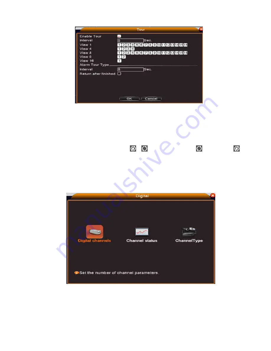
Pic 3.3.7 tour setup 

Interval

Set the tour switch interval time. The range is 5-120 seconds. 

Alarm tour

set the interval time to shift alarm tour, range is 5-120 seconds, choose return when 

alarm ends, when alarm link to tour, system will auto shift to six-view after alarm finished. 

Note

at preview mode, click upper right icon 

  / 

  can turn on / off tour


  mean turn on, 


mean turn off

.


3.3.8    Channel manage 

Digital manage including digital channel, channel status, and channel mode   


Pic 3.3.8.0 channel manage interface 

  Digital channel: 

Summary of Contents for NVR 2708

Page 1: ...1 USER MANUAL NVR 2708 NVR2716...

Page 2: ...Before the dust cleaning please switch off the power and unplug it Do not disassemble or repair the NVR by yourself Do not replace the components by yourself Environment Please place and use the NVR b...

Page 3: ...4 1 2 Front panel 4 1 3 Rear panel 5 2 Basic operation 5 2 1 Turn on 6 2 2 Turn off 6 2 3 System Login 6 2 4 Preview 7 2 5 Desktop shortcut menu 8 3 Main menu 18 3 1 Record 18 3 2 Alarm Function 21 3...

Page 4: ...tion in the front panel and the interface specification in the real panel are in the specification Please check the product type in the front panel whether is accordant with the product type you order...

Page 5: ...vigation buttons to control the connected PTZ camera not included Press to move cursor up in PTZ mode press to pan camera up Press to move cursor down in PTZ mode press to pan camera down Press to mov...

Page 6: ...n automatically backup video and resume previous working status after power failure 2 Replace the hard disk Before replacing the hard disk the power supply switch in the real panel must be turned off...

Page 7: ...our the account will be unlocked automatically For your system security please modify your password after first login 2 4 Preview You can right click mouse to choose the switch between the windows The...

Page 8: ...w and it s extra stream s resolution under multi screen 2 5 Desktop shortcut menu In preview mode you can right click mouse to get a desktop shortcut menu as the picture 2 2 shows The menu includes ma...

Page 9: ...Pic 2 5 1 Main menu 2 5 2 Playback There are two methods for you to play the video files in the hard disk 1 In the desktop shortcut menu 2 Main Menu Record playback Note The hard disk which saves the...

Page 10: ...e listed files that accord with the searching criteria File information Look up the found file information Playback control See detail in below chart Button Function Button Function Play Pause Backwar...

Page 11: ...it is in recording status You can use desktop shortcut menu or click Main menu Record Record Conf to enter the recording control interface Pic 2 5 3 Record Mode Schedule Record according to the confi...

Page 12: ...nd with protocol correctly set also Operation interface is as followed The functions include PTZ direction control step zoom focus iris preset operation tour pattern border assistant switch light swit...

Page 13: ...rns to the setting position 1 Preset option Set a location for the preset procedure is as follows Step1 in Picture 2 5 5 0 click the Direction button will turn into preset position click the Settings...

Page 14: ...lete tour preset which has been set up Step 3 repeat step1 and step2 until set out all the preset designated Cruise lines Remove Preset Please input preset value in the blank click Remove Preset butto...

Page 15: ...in the value blank then click Scan button PTZ begins to work on the scan line Click Stop button to stop 4 Boundary Scan In a horizontal line set up a line call scan PZT repeat operation according to...

Page 16: ...in the value blank then click Scan button PTZ begins to work on the scan line Click Stop button to stop 5 Horizontal Rotating Click Horizontally Rotating button PTZ begins to rotate horizontally relat...

Page 17: ...click Page Shift button enter the Picture 2 5 5 5 PTZ Main Menu the menu itself can be control by the menu control buttons 2 5 6 Output Adjust Adjust TV output area parameters You can use the desktop...

Page 18: ...luding Record Playback Backup 3 1 1 Record Configuration Set the recording parameters in the surveillance channel The system is set 24 hours consecutive recording in the first startup You can enter Ma...

Page 19: ...of common recording The recording will start only in the set range Record type Set recording type regular detection or alarm Regular Perform the regular recording in the set time section The video fil...

Page 20: ...ed up You can choose the backup file according to the type channel and time Picture 3 1 3 1 Backup Remove Clear the file information Add Show the file information satisfying the set file attributes Ba...

Page 21: ...alarm output abnormality 3 2 1 Motion Detect When system detects the motion signal that reaches the set sensitivity the motion detect alarm is on and the linkage function is turned on Note Advanced bu...

Page 22: ...00 seconds Record channel Choose the recording channel multiple option supportive Trigger the video signal when the alarm is turned on Note Set in the Record Conf and perform the linkage recording Sta...

Page 23: ...h buzz 3 2 2 Video Blind When the video image is influenced by the environment such as bad brightness or reaching the set sensitivity parameter the video blind function is turned on and the linkage fu...

Page 24: ...is turned on Note Advanced button is the same as right click Pic 3 2 4 Alarm input Set method refer to chapter 3 3 1 Motion detect 3 2 5 Alarm output Refer to chapter 2 5 4 3 2 6 Abnormal Analysing a...

Page 25: ...e dialog box come out of the main screen Buzzer Device will have one long nosie di while alarm is happening 3 3 System setup Set the system parameters such as General Network Net service GUI display P...

Page 26: ...w etc HDD full Choose stop record Stop recording when the hard disk is full Choose overwrite Cover the earliest recording files and continue recording when the hard disk is full DVR No Only when the a...

Page 27: ...rovider The address must be set and reboot then it works Media port Default 34567 HTTP port Default 80 HS Download Transfer Policy There are three strategies self adaption image quality precedence and...

Page 28: ...up your system Then the NVR will build a network connection based on PPPoE The IP address will change into dynamic IP address after above operation is well done Operation After PPPoE dialing successfu...

Page 29: ...AIL setup SMTP server Email server address It could be an IP address or domain name Domain name can be translated only it is the correct DNS configuration Port Email server port number SSL Decide whet...

Page 30: ...istered by DDNS Password Provide the password registered by DDNS When the DDNS is successfully configured and start you can connect the domain name in the IE address column to visit Note The DNS setup...

Page 31: ...FTP Password Password of user Anonymous enable anonymous no need setting user name and password Max File Length Max length for upload files at every packed default 128M Dir Name The directory of uplo...

Page 32: ...hen chynchronously Note Please set up server before using DDNS Alarm center When alarm occurring report alarm information to alarm server Pic 3 3 3 8 Alarm center setup Protocol type GENERAL Enable To...

Page 33: ...sit the device by mobile please make a router mapping of this port and use mobile software to monitor and operate it by protocol Pic 3 3 3 10 Mobile Monitor Setup Enable Select it to make sure abnorma...

Page 34: ...Port for the device when mobile monitor it need this port WIFI NVR connect to wireless router via WIFI module then to visit it through IP address the precondition of using this function is to make su...

Page 35: ...and VLC software This function only for monitor but can not control the device Pic3 3 3 13 RTSP setup Enable means enable tick it firstly before setting Port the default port is 554 Cloud Enable mean...

Page 36: ...ort Alarm Status Display the system alarm status in the surveillance window Transparency Choose the background image transparency The range is 128 255 Resolution set display resolution 3 3 5 RS485 Pic...

Page 37: ...Common serial port is used to debug and update program or set up specific serial port Baud rate Choose the corresponding baud rate length Data bits Include 5 8 options Stop bits Include 2 options Par...

Page 38: ...20 seconds choose return when alarm ends when alarm link to tour system will auto shift to six view after alarm finished Note at preview mode click upper right icon can turn on off tour mean turn on m...

Page 39: ...ttings Time Synchronization Tick it means the time of this channel and device is the same Connection Mode can be singe connect or multi ink multi link modes can connect to several devices device will...

Page 40: ...what you like default is IPC Protocol Default is NETIP can choose ONVIF Remote channel User can input remote channel title from the device that you want to connect remotely Stream Default is main stre...

Page 41: ...Status Channel status is to show the status of all the digital channel When there is what existing status Including Max Resolution this Resolution Connection Status See as follow pictture Pic 3 3 8 5...

Page 42: ...solution that the channel supported then a red X will be shown on the preview image for example Under full digital channel mode Max resolution of channel 3 is D1 if it was connected to a device with r...

Page 43: ...nt can read data but can not write data Redundant Disk Double backup the video files in the write read disk Pic 3 4 1 HDD manage 3 4 2 Account Manage the user purview Note 1 The character length is 8...

Page 44: ...ssess the user control purview can modify his her own or other users password Pic 3 4 2 1 modify password Add user Add a user in the group and set the user purview Enter the menu interface and input t...

Page 45: ...hut down the equipment real time surveillance playback record setting video backup and so on Pic 3 4 2 3 add group Delete User Delete the current user Choose the user and click delete user button Dele...

Page 46: ...box then the user will be frozen after connection stopped and will not log in until device reboot Pic 3 4 3 online user 3 4 4 Output adjust Refer to chapter 2 5 7 3 4 5 Auto Maintain The user can set...

Page 47: ...rade file choose the upgrade file 3 4 8 Device Info Provide device interface info like audio in alarm in out to be conveniently used for user Pic 3 4 8 device info 3 4 9 Import Export Users can export...

Page 48: ...y residual capability the recording time and so on Pic 3 5 1 HDD Info Tips means that the hard disk is normal X means that the hard disk is broken down means that there is no hard disk If the user nee...

Page 49: ...management alarm affair recording operation account management file management and so on Set the time section to look up and click the look up button The log information will display as a list one pa...

Page 50: ...values during live viewing press to view channels in full screen 4 QUAD Press to switch between quad and split screen displays 5 PTZ Press to open the PTZ control window 6 Playback controls Increase...

Page 51: ...rsor in menus right Move cursor in menus left Move cursor in menus down Enter In menus press to confirm selections during playback and preview press to view system information TIP When using the remot...

Reviews: