SIG MID-STAR 40 Building And Flying Instructions Download Page 9

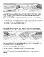
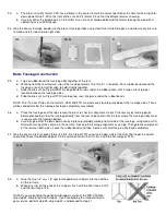
21. Finish off the bottom center sheeting, again using 1/16" balsa.
 
22.

 
Give the wing a final sanding with a long sanding block. Sand just enough to take off any prominent high spots or bumps. 
Excessive sanding may distort the airfoil shape. Any dents or gouges in the wood can be filled with a lightweight wood filler.

 
23.

 
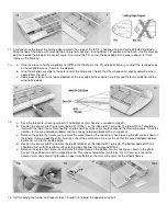
The 1" wide fiberglass tape can be applied to the wing center joint (top and bottom) using one of the following methods.


Remove the tape from the servo cutout 
area after the glue is dry.


METHOD 1: 

a. Coat the wing center joint with slow-drying epoxy glue.  
b. Lay the tape on the top of the glue  

c. Holding one end of the tape so it won't slip, "squeegee" the glue through the tape with a small paddle 

of scrap balsa. Scrape over the tape several times with the paddle to smooth the tape and remove 
any excess glue.  

d. When dry, sand lightly to remove any rough spots. Try not to sand into the fiberglass tape itself. 


METHOD 2: 

a. Cut the tape to length, then lightly spray one side with a spray adhesive (such as 3M "77").  
b. Position the tape on the wing center joint.  

c. Soak the tape with CA. The spray adhesive simply holds the tape in place - it won't affect the strength 

of the CA. A second coat of CA will help to fill in the weave of the fiberglass, resulting in a smoother 
surface. Rub the second coat with your finger (protected with plastic wrap - keep it moving!) to 
smooth out the glue. Use a fan to keep the CA fumes away from your face.  

d. When dry, sand lightly to remove any rough spots. Try not to sand into the fiberglass tape itself. 


Ailerons

 
24.

 
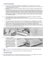
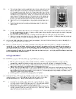
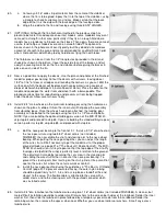
The leading edge of each aileron is pre-shaped, but they need to be sanded lightly to a smooth, round contour. Position the 
ailerons on the back of the wing, leaving a 1/32" gap between the inboard ends of the ailerons and the outboard ends of the 
torque rod blocks. Mark the locations for the torque rods, then slot and drill the aileron leading edges to receive the torque 
rod wires.

 
25.

 
Trial fit the ailerons to the torque rods. 
Once they fit, temperarily tape the 
ailerons in place and sand their outboard 
ends to match the curve of the wingtips. 
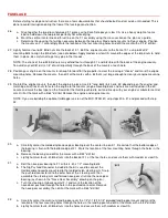
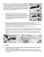
The outer edge of the ailerons and the 
scrap balsa on the T.E. of the wingtips 
should be rounded off so that they blend 
together perfectly.


Summary of Contents for MID-STAR 40

Page 1: ...as no leading edge sheeting which helps speed construction The simple pre cut balsa tail parts also save time The model can be completely covered with iron on film with only a small amount of painting required One important decision that you will need to make before building is whether to use tricycle landing gear on your MID STAR 40 or make it a taildragger New pilots who are transitioning from a...

Page 2: ...ing the plywood fuselage parts The extra thickness allows the glue to fill small gaps but it dries a little slower than thin CA If you want only one type of CA use medium thickness Sig CA Slow This thickest formula is good for filing large gaps and building up strong fillets at joints requiring extra strength It also dries slow enough to allow you to apply it to one part and position it on another...

Page 3: ...n you can start on or proceed with another part Work can even go forward on several sections of the same assembly at the same time such as the front and rear sections of the fuselage Keep in mind that the number sequence used in these instructions was chosen as the best way to explain the building of each major component and is not intended to be followed in exact one two three fashion Start on th...

Page 4: ...g center and tailwheel wire 2 6 3 4 x27 3 Color Decal 1 Full Size Printed Plan 1 Photo Illustrated Instruction Booklet 1 The Basics Of Radio Control Booklet Hardware 4 2 x1 2 Sheet Metal Screws for control horns 2 4 40 x3 8 Flat Head Mounting Bolts for hatch 1 4 40 x 3 8 Mounting Bolt for canopy hold down 8 4 40 x1 2 Mounting Bolts for nose gear bearing and landing gear 4 6 32 x3 4 Mounting Bolts ...

Page 5: ... piles to avoid confusion during building WING CONSTRUCTION Before beginning wing construction carefully splice together the Left Wing Panel plans so that the X and Y indicators meet Use a straightedge to double check the alignment of the plans before taping them at the seam Tape or pin the plans to your building board and protect them with a layer of waxed paper Build each wing half separately 1 ...

Page 6: ... step Otherwise you may find it difficult to remove your wing from the board later 6 Pieces for the top center sheeting should be cut from the 1 16 x 3 x 30 balsa provided in the kit Again Sig Bond is recommended for the front and rear edges of the sheeting to make it easier to sand the joints smooth Also use Sig Bond on the center W 1 rib The sheeting can be glued to the ribs on each end using CA...

Page 7: ...tout guide 1 RCG 1 on the inboard W 1 wing rib The top of RCG 1 should be flush with the top of the center sheeting and the notches at the rear should fit around the main wing spars Trace the notches for the wing hold down dowel and the canopy hold down block with a sharp pencil c Remove the guide then measure and mark the cutout area on the top center sheeting using the dimension shown in the pho...

Page 8: ...ng When dry trim BP flush with the bottom center sheeting 17 a The aileron torque rods have been pre bent so that the threaded portion leans rearward slightly inside the fuselage see the W 1 wing rib cross section on the plans That small angle will provide your MID STAR 40 with a bit of differential movement more up that down in the ailerons which makes for smoother rolling characteristics Prepare...

Page 9: ...3M 77 b Position the tape on the wing center joint c Soak the tape with CA The spray adhesive simply holds the tape in place it won t affect the strength of the CA A second coat of CA will help to fill in the weave of the fiberglass resulting in a smoother surface Rub the second coat with your finger protected with plastic wrap keep it moving to smooth out the glue Use a fan to keep the CA fumes a...

Page 10: ...hing aircraft lock nuts to fasten the engine to the mounts engine mounting bolts and nuts are not included in the kit Locate and mark the best spot on the firewall for the throttle pushrod to exit and line up with your engine s carburetor control arm Drill at the mark with a 9 64 drill bit Remove the engine and engine mounts NOTE If you are building the optional taildragger version of the MID STAR...

Page 11: ...age sides These will be sanded off after the fuselage has been completely assembled 36 a Place the fuselage over the top view on the plans to check its alignment Correct if necessary by twisting gently before proceeding View the fuselage directly from the rear to be certain that the joint where the fuselage sides meet is square with the fuselage bottom b Carefully glue all of the parts permanently...

Page 12: ...m as necessary to clear the blind nuts on the back of F 1 Apply slow CA to the braces and press them firmly in place c Install the die cut Lite Ply tank floor so that it is sealed on the fuselage doublers and against the back of F 1 then glue it in place 42 a Glue the 1 4 x1 x3 5 6 balsa nose brace to the top of the fuselage and F 1 b When dry hold the die cut 3 32 plywood hatch tongue in position...

Page 13: ...serve as a wing hold down dowel Save the remaining piece for the canopy hold down dowel b Sharpen one end of the wing hold down dowel to a point keep the point symmetrical and centered With the hatch removed push the dowel into the hole in F 2 so that only the point sticks out into the wing opening Slide the wing into position making sure it is centered on the fuselage When you remove the wing the...

Page 14: ...bolts 52 a The servos need to be mounted in the fuselage so that the nylon pushrods can be routed properly with the least amount of curvature Refer to Chapter 2 of The Basics Of Radio Control and the plans for information on where and how to mount the servos in the fuselage Start by cutting two 3 1 4 long servo rails from the supplied 3 8 sq basswood Use the servo tray provided with your radio to ...

Page 15: ...nk compartment Mark the locations of the fuel lines on F 1 remove the fuel tank then drill holes through F 1 at the marks using a drill bit that s the same diameter as the fuel tubing you plan to use You should also redrill the holes for the throttle and nosewheel pushrods 9 64 dia since they were both probably covered up by the triangle braces installed in step 41 Canopy Installation 59 NOTE The ...

Page 16: ...canopy b The canopy hold down screw will pass through the extended front flange Tape the canopy in place on the model and carefully mark the location of the hole for the canopy hold down screw Be certain that the hole will pass directly through the center of the canopy hold down block in the wing c Drill through the canopy flange and canopy hold down block at the same time with a 1 8 drill bit 65 ...

Page 17: ...dge using the hinge line as a guide 70 The top of the fin or rudder may need sanding so that they line up when installed Temporarily pin or tape the stabilizer and fin on the back of the fuselage then tape the rudder to the fin so that its bottom edge is aligned with the fuselage bottom Remove the fin and rudder which are still taped together and sand the top edges until they match NOTE If you are...

Page 18: ...ow access to needle valves carburettor adjusting screws etc When satisfied remove the engine and touch up the cutouts with some sandpaper Since it s too difficult to apply covering material inside the engine compartment it must be fuel proofed using several coats of clear dope or two coats of polyester glass resin sanded between coats Finish off the engine area with a few coats of colored Sig Supe...

Page 19: ...iece of material extending it about 1 8 past the outside edges of the plates again to provide an area for overlap Cover the main portion of the wing starting with the bottom and then the top so that the seams will be on the bottom where they will be less visible The top covering should overlap the full width of the leading trailing edge Wait until both the top and bottom pieces of covering materia...

Page 20: ...nutes the joint should be flexed to full deflection in each direction a couple of dozen times to reduce the stiffness Don t worry about shortening the life of the hinges as they are almost indestructible 76 The rudder is hinged in the same manner as above but it is easier to install AFTER the fin has been glued to the fuselage Cut slots for three hinges now 3 slots in the rudder two in the fin and...

Page 21: ...n the inner nut will help keep the assembly from vibrating loose Once the wheels have been attached the landing gear assembly can be bolted to the fuselage using four 4 40 x 1 2 mounting bolts NOTE If you are building the optional taildragger version of the MID STAR 40 skip step 84 and proceed to step 85 If you are building the standard tricycle gear version perform step 84 skip step 85 and procee...

Page 22: ...length of 3 1 2 measuring from the threaded end Install the threaded rod in the nylon tubing smooth end first so that approximately 1 2 of the threaded portion remains exposed The metal rod will help prevent the nylon tubing from buckling under flight loads Thread the R C link onto the end of the pushrod until the rudder is neutral then repeat the procedure for the elevator The aileron servo can b...

Page 23: ...ing and using it that you would with a can of gasoline or a bottle of poison Remember that it is possible to lose control of a model airplane Do not fly in locations where the model may hit people or damage property if loss of control occurs Check your model and equipment regularly to insure it is in safe operating condition FLYING The MID STAR 40 is a fun aircraft to fly but it is not a basic tra...

Page 24: ...g final approach Slow the model down during the entire approach by slowly feeding in up elevator Just before the model touches flare the landing by carefully feeding in more up elevator Hold the model just inches off the ground until your elevator stick is pulled all the way back The MID STAR 40 should settle in for a perfect nose high landing with a short rollout MODELER S TIP The canopy gives th...

Page 25: ...pm Central Copyright SIG Mfg Co Inc SIG MFG CO INC Montezuma Iowa 50171 0520 LIMIT OF LIABILITY In use of our products Sig Mfg Co s only obligation shall be to replace such quantity of the product proven to be defective User shall determine the suitability of the product for his or her intended use and shall assume all risk and liability in connection therewith ...

Reviews: