SIG MID-STAR 40 Building And Flying Instructions Download Page 2

.


Recommended Glues

 
There are so many different glues available today for model construction that it can be confusing to even the experienced 
modeler. To simplify matters, most glues can be classified as one of four basic types: 

1. Fast-drying cyanoacrylate adhesives ( abbreviated in these instructions as "CA") such as SIG CA, Hot Stuff, Jet, etc .....  
2. Easy-to-use water-base wood glues such as SIG-BOND (yellow) and SIG SUPER-WELD (white).  
3. Super strong two-part epoxy glues such as SIG KWIK-SET (5-minute cure) and SIG EPOXY (3-hour cure).  
4. Traditional solvent-base model cements such as SIG-MENT. 

Each of these types has different characteristics and advantages. Often times, the choice of which type to use is strictly a matter 
of personal preference based on your prior experience with a previous model. However, because of the vast use of Lite-Ply and 
hardwoods in the MID-STAR 40, we have found that the CA glues seem to work the best for general construction. In fact, the 
construction sequence of the fuselage is designed with the use of CA glue in mind. Other glues could be used, but CA is 
recommended as our first choice because of its ability to penetrate an already assembled joint. In other words, the fuse parts 
can first be assembled dry (without glue), the alignment checked and adjusted, and then the glue can be applied to the joints. 
You should also have on hand some epoxy (both 5-minute and slow dry) and Sig-Bond because these glues are called out in 
several of the steps in this book. 
 
Sig CA, like most brands of cyanoacrylates, comes in three viscosities - thin, medium and thick. An accelerator spray and 
debonder are also available and are described below. 

Sig CA Thin

 - Watery in consistency, thin CA should only be used when the two parts to be joined are in perfect contact 

with zero gap. Capiliary action pulls this glue deep into the wood resulting in a very strong bond and it dries in just a few 
seconds. Thin CA can be used to tack assemblies together, but these joints should be glued again later with medium or 
thick CA. Thin CA is also necessary for installing EASY HINGES.  

Sig CA Medium

 - Our medium thickness CA is excellent for almost any step during construction, and is particularly 

recommended for gluing the plywood fuselage parts. The extra thickness allows the glue to fill small gaps, but it dries a 
little slower than thin CA. If you want only one type of CA, use medium thickness.  

Sig CA Slow

 - This thickest formula is good for filing large gaps and building up strong fillets at joints requiring extra 

strength. It also dries slow enough to allow you to apply it to one part and position it on another before it dries. (With thin 
and medium CA's, the parts must be in contact and positioned correctly before glue application.) This feature is useful 
when laminating large sheeted areas like a fuselage side and a fuselage doubler.  

Sig Kwik-Shot Accellerator

 - Spraying accellerator on CA (any thickness) will cure it almost instantly. Although CA is 

fast, it's sometimes nice to speed it up even more.  

Debonder

 - This can be used to separate parts, but you'll probably use it for unsticking your fingers more than anything 

else! 


CAUTION

Some people have experienced allergic reactions when exposed to epoxy or cyanoacrylate glues. This is very rare. 
However, it is always important that such glues, and also paints, thinners, and solvents, be used with adequate ventilation 
to carry fumes away.


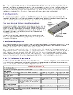
Engines, Propellers, And Mufflers

 
There is a tremendous variety of engines available in the size range 
specified for the MID-STAR 40. Both 2-stroke and 4-stroke engines 
work equally well in this model, so choose your favourite type, 
keeping in mind the type or performance that you wish the model to 
have.


Recommended Engine Range: .30 - .40 2-Stroke

.40 - .50 4-Stroke

 
If you want maximum aerobatic capability and vertical performance, use an engine towards the upper end of the recommended 
size range. If the MID-STAR 40 is your first move up from a trainer, engine sizes from the bottom of the range may suit you 
better. Engines at the bottom of the range will still put the MID-STAR 40 through most aerobatic maneuvers.  
 
Use only propellers recommended in the instructions supplied with your engine. If you use a very high-power engine in your 
model (such as a schneurle-ported 2-stroke .40), it's recommended that you opt for a propeller with a relatively large diameter 
and low-pitch. This will give you loads of pulling power during maneuvers without a lot of excess speed. If you build the tricycle-
gear version and fly off grass, the prop diameter should be kept at 11" or less. If you fly off a hard-surface, you can use up to a 
12" dia. prop.

Summary of Contents for MID-STAR 40

Page 1: ...as no leading edge sheeting which helps speed construction The simple pre cut balsa tail parts also save time The model can be completely covered with iron on film with only a small amount of painting required One important decision that you will need to make before building is whether to use tricycle landing gear on your MID STAR 40 or make it a taildragger New pilots who are transitioning from a...

Page 2: ...ing the plywood fuselage parts The extra thickness allows the glue to fill small gaps but it dries a little slower than thin CA If you want only one type of CA use medium thickness Sig CA Slow This thickest formula is good for filing large gaps and building up strong fillets at joints requiring extra strength It also dries slow enough to allow you to apply it to one part and position it on another...

Page 3: ...n you can start on or proceed with another part Work can even go forward on several sections of the same assembly at the same time such as the front and rear sections of the fuselage Keep in mind that the number sequence used in these instructions was chosen as the best way to explain the building of each major component and is not intended to be followed in exact one two three fashion Start on th...

Page 4: ...g center and tailwheel wire 2 6 3 4 x27 3 Color Decal 1 Full Size Printed Plan 1 Photo Illustrated Instruction Booklet 1 The Basics Of Radio Control Booklet Hardware 4 2 x1 2 Sheet Metal Screws for control horns 2 4 40 x3 8 Flat Head Mounting Bolts for hatch 1 4 40 x 3 8 Mounting Bolt for canopy hold down 8 4 40 x1 2 Mounting Bolts for nose gear bearing and landing gear 4 6 32 x3 4 Mounting Bolts ...

Page 5: ... piles to avoid confusion during building WING CONSTRUCTION Before beginning wing construction carefully splice together the Left Wing Panel plans so that the X and Y indicators meet Use a straightedge to double check the alignment of the plans before taping them at the seam Tape or pin the plans to your building board and protect them with a layer of waxed paper Build each wing half separately 1 ...

Page 6: ... step Otherwise you may find it difficult to remove your wing from the board later 6 Pieces for the top center sheeting should be cut from the 1 16 x 3 x 30 balsa provided in the kit Again Sig Bond is recommended for the front and rear edges of the sheeting to make it easier to sand the joints smooth Also use Sig Bond on the center W 1 rib The sheeting can be glued to the ribs on each end using CA...

Page 7: ...tout guide 1 RCG 1 on the inboard W 1 wing rib The top of RCG 1 should be flush with the top of the center sheeting and the notches at the rear should fit around the main wing spars Trace the notches for the wing hold down dowel and the canopy hold down block with a sharp pencil c Remove the guide then measure and mark the cutout area on the top center sheeting using the dimension shown in the pho...

Page 8: ...ng When dry trim BP flush with the bottom center sheeting 17 a The aileron torque rods have been pre bent so that the threaded portion leans rearward slightly inside the fuselage see the W 1 wing rib cross section on the plans That small angle will provide your MID STAR 40 with a bit of differential movement more up that down in the ailerons which makes for smoother rolling characteristics Prepare...

Page 9: ...3M 77 b Position the tape on the wing center joint c Soak the tape with CA The spray adhesive simply holds the tape in place it won t affect the strength of the CA A second coat of CA will help to fill in the weave of the fiberglass resulting in a smoother surface Rub the second coat with your finger protected with plastic wrap keep it moving to smooth out the glue Use a fan to keep the CA fumes a...

Page 10: ...hing aircraft lock nuts to fasten the engine to the mounts engine mounting bolts and nuts are not included in the kit Locate and mark the best spot on the firewall for the throttle pushrod to exit and line up with your engine s carburetor control arm Drill at the mark with a 9 64 drill bit Remove the engine and engine mounts NOTE If you are building the optional taildragger version of the MID STAR...

Page 11: ...age sides These will be sanded off after the fuselage has been completely assembled 36 a Place the fuselage over the top view on the plans to check its alignment Correct if necessary by twisting gently before proceeding View the fuselage directly from the rear to be certain that the joint where the fuselage sides meet is square with the fuselage bottom b Carefully glue all of the parts permanently...

Page 12: ...m as necessary to clear the blind nuts on the back of F 1 Apply slow CA to the braces and press them firmly in place c Install the die cut Lite Ply tank floor so that it is sealed on the fuselage doublers and against the back of F 1 then glue it in place 42 a Glue the 1 4 x1 x3 5 6 balsa nose brace to the top of the fuselage and F 1 b When dry hold the die cut 3 32 plywood hatch tongue in position...

Page 13: ...serve as a wing hold down dowel Save the remaining piece for the canopy hold down dowel b Sharpen one end of the wing hold down dowel to a point keep the point symmetrical and centered With the hatch removed push the dowel into the hole in F 2 so that only the point sticks out into the wing opening Slide the wing into position making sure it is centered on the fuselage When you remove the wing the...

Page 14: ...bolts 52 a The servos need to be mounted in the fuselage so that the nylon pushrods can be routed properly with the least amount of curvature Refer to Chapter 2 of The Basics Of Radio Control and the plans for information on where and how to mount the servos in the fuselage Start by cutting two 3 1 4 long servo rails from the supplied 3 8 sq basswood Use the servo tray provided with your radio to ...

Page 15: ...nk compartment Mark the locations of the fuel lines on F 1 remove the fuel tank then drill holes through F 1 at the marks using a drill bit that s the same diameter as the fuel tubing you plan to use You should also redrill the holes for the throttle and nosewheel pushrods 9 64 dia since they were both probably covered up by the triangle braces installed in step 41 Canopy Installation 59 NOTE The ...

Page 16: ...canopy b The canopy hold down screw will pass through the extended front flange Tape the canopy in place on the model and carefully mark the location of the hole for the canopy hold down screw Be certain that the hole will pass directly through the center of the canopy hold down block in the wing c Drill through the canopy flange and canopy hold down block at the same time with a 1 8 drill bit 65 ...

Page 17: ...dge using the hinge line as a guide 70 The top of the fin or rudder may need sanding so that they line up when installed Temporarily pin or tape the stabilizer and fin on the back of the fuselage then tape the rudder to the fin so that its bottom edge is aligned with the fuselage bottom Remove the fin and rudder which are still taped together and sand the top edges until they match NOTE If you are...

Page 18: ...ow access to needle valves carburettor adjusting screws etc When satisfied remove the engine and touch up the cutouts with some sandpaper Since it s too difficult to apply covering material inside the engine compartment it must be fuel proofed using several coats of clear dope or two coats of polyester glass resin sanded between coats Finish off the engine area with a few coats of colored Sig Supe...

Page 19: ...iece of material extending it about 1 8 past the outside edges of the plates again to provide an area for overlap Cover the main portion of the wing starting with the bottom and then the top so that the seams will be on the bottom where they will be less visible The top covering should overlap the full width of the leading trailing edge Wait until both the top and bottom pieces of covering materia...

Page 20: ...nutes the joint should be flexed to full deflection in each direction a couple of dozen times to reduce the stiffness Don t worry about shortening the life of the hinges as they are almost indestructible 76 The rudder is hinged in the same manner as above but it is easier to install AFTER the fin has been glued to the fuselage Cut slots for three hinges now 3 slots in the rudder two in the fin and...

Page 21: ...n the inner nut will help keep the assembly from vibrating loose Once the wheels have been attached the landing gear assembly can be bolted to the fuselage using four 4 40 x 1 2 mounting bolts NOTE If you are building the optional taildragger version of the MID STAR 40 skip step 84 and proceed to step 85 If you are building the standard tricycle gear version perform step 84 skip step 85 and procee...

Page 22: ...length of 3 1 2 measuring from the threaded end Install the threaded rod in the nylon tubing smooth end first so that approximately 1 2 of the threaded portion remains exposed The metal rod will help prevent the nylon tubing from buckling under flight loads Thread the R C link onto the end of the pushrod until the rudder is neutral then repeat the procedure for the elevator The aileron servo can b...

Page 23: ...ing and using it that you would with a can of gasoline or a bottle of poison Remember that it is possible to lose control of a model airplane Do not fly in locations where the model may hit people or damage property if loss of control occurs Check your model and equipment regularly to insure it is in safe operating condition FLYING The MID STAR 40 is a fun aircraft to fly but it is not a basic tra...

Page 24: ...g final approach Slow the model down during the entire approach by slowly feeding in up elevator Just before the model touches flare the landing by carefully feeding in more up elevator Hold the model just inches off the ground until your elevator stick is pulled all the way back The MID STAR 40 should settle in for a perfect nose high landing with a short rollout MODELER S TIP The canopy gives th...

Page 25: ...pm Central Copyright SIG Mfg Co Inc SIG MFG CO INC Montezuma Iowa 50171 0520 LIMIT OF LIABILITY In use of our products Sig Mfg Co s only obligation shall be to replace such quantity of the product proven to be defective User shall determine the suitability of the product for his or her intended use and shall assume all risk and liability in connection therewith ...

Reviews: