


.
FUSELAGE
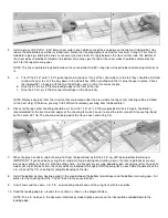
Before starting fuselage construction, there are a few subassemblies that should be built and set aside until needed. This is
done to avoid interruption during the flow of the fuselage construction.
26.
a. Glue together the two die-cut plywood F-1 pieces using Kwik-Set epoxy or slow CA. Use a heavy weight of some
kind to hold down the two pieces perfectly flat while drying.
b. Mark the vertical centerline and thrust line on the F1 assembly using the cross-section on the plan as a guide.
c. Determine the spacing that will be necessary between the two glass filled engine mounts to fit your engine. Position
the mounts on F-1 accordingly. Mark the location of the four mounting holes and drill them out with a 3/16" drill bit.
27.
Lightly hammer four 6-32 blind nuts into the back of F-1. Bolt the engine mounts to the front of F-1 using 6-32x3/4"
mounting bolts to align the blind nuts (see note below). Apply medium or slow CA around the edges of the blind nuts to hold
them in place. Be careful not to get any glue in the threads.
NOTE: The shank of the 6-32 blind nuts may extend too far through F-1 and interfere with the back of the engine mounts.
To avoid any conflict, drill a 1/4" dia. relief partially through the back of the mounts at each hole.
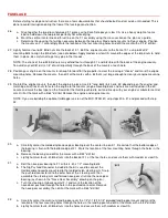
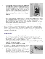
28.
Position your engine on the mounts far enough forward for the propeller to clear the fuselage "cheeks" and mark the engine
mounting holes. Remove the mounts, then drill at the marks with a bit that's just large enough to clear your engine mounting
holes.
29.
Re-intall the engine mounts, then bolt the engine in place. Use 3/4" long bolts (4-40 or 6-32, depending on the engine) and
matching aircraft lock nuts to fasten the engine to the mounts (engine mounting bolts and nuts are not included in the kit).
Locate and mark the best spot on the firewall for the throttle pushrod to exit and line up with your engine's carburetor control
arm. Drill at the mark with a 9/64" drill bit. Remove the engine and engine mounts.
NOTE: If you are building the optional taildragger version of the MID-STAR 40, skip steps 30 & 31 and proceed with step
32.
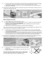
30.
a. Carefully center the molded nylon nose gear bearing over the center line on F-1. Be certain that the bottom edge of
the bearing is flush with the bottom edge of F-1. Mark the location of the four mounting holes through the holes in the
bearing.
b. Remove the bearing and drill at the marks with a 5/32" drill bit.
c. Lightly hammer four 4-40 blind nuts into the back of F-1 at the four holes, and secure them with medium or slow CA.
31.
a. Bolt the nose gear bearing to F-1 with 4 4-40 x 1/2" mounting bolts.
b. The Sig Pushrod Connector included in the kit is used to connect the
flexible cable nosewheel pushrod to the molded nylon steering arm. Snap
the pushrod connector onto the outer hole of the s teering arm, then
assemble the steering arm and formed nose gear strut into the nose gear
bearing (as shown in the "Nose Gear Assembly" drawing on the plan).
c. Turn the steering arm back against F-1 and mark the location of the
nosewheel pushrod through the hole in the pushrod connector. Remove
the nose gear assembly, then drill at the mark with a 9/64" drill bit.
32.
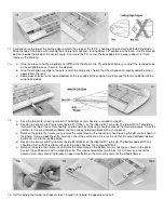
a. Carefully center the aluminum landing gear over the 1/4"x1-1/2"x3-1/4" plywood landing gear mount and mark the
location of the four mounting holes through the holes in the landing gear and drill at the marks with a 5/32" drill bit.
b. Lightly hammer four 4-40 blind nuts into the holes and secure them with medium or slow CA.