


.
55.
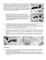
a. The nylon pushrods must be supported at each former to keep them from
flexing under load. Use the die-cut Lite-Ply pushrod straps, F-3S and F-
4S, to support the pushrods. Notice that the pushrod straps haven't been
marked for pushrod location because the routing of the pushrods will vary
with different servo installations. Ideally, you want to have the pushrods to
come through F-3S pointed directly at the servo arms of the rudder and
elevator servos. Carefully mark drill locations on the pushrod straps for
the two nylon pushrods. Drill at the marks with a 3/16" drill bit.
b. Slide F-4S then F-3S into position on the pushrods, but don't glue them
yet.
c. Cut off the front ends of the outer pushrod tubes about 2" short of the
se4rvo arms.
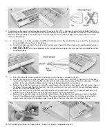
56.
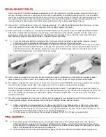
a. Cut two 2-56 x10" threaded rods to an overall length of 2-1/2", measuring from the threaded end. Put a "Z" bend in
the non threaded end of the rods. Of course, another type of servo connector may be used if you prefer (see page 7
of "The Basics Of Radio Control").
b. Screw the threaded end of the rods completely into the two 130" o.d. x 30" nylon inner pushrod tubes.
c. Slide the inner pushrod tubes into the outer tubes from the servo end. Install the "Z" bends (or your altenate servo
connectors) on the servo arms and hook them into the servos.
57.
With the pushrods hooked up to the servos you can now glue F-3S and F-4S to the front of F-3 and F-4, repsectively, in
such a way to keep the bends at a minimum.
58.
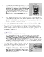
This is a good time to plan your fuel tank installation and routing of fuel lines through F-1 (see "Engine And Fuel Tank
Installation" in the "Final Assembly" section of these instructions). Assemble your fuel tank (following the manufacturer's
instructions and position it in the fuel tank compartment. Mark the locations of the fuel lines on F-1, remove the fuel tank,
then drill holes through F-1 at the marks using a drill bit that's the same diameter as the fuel tubing you plan to use. You
should also redrill the holes for the throttle and nosewheel pushrods (9/64" dia.), since they were both probably covered up
by the triangle braces installed in step 41.
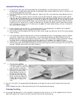
Canopy Installation
59.
NOTE: The wing must be finished through step 25 before proceeding.
a. Trim the plastic canopy base to the molded-in trim lines. With the wing firmly bolted to the fuselage, tape the
canopy base in position on top of the wing. Confirm that the front of the "console" is centered on the wing.
b. Trim around the clear plastic canopy at the molded-in trim lines, then trial fit it on the model. Trim or sand the back
edge of the canopy until it fits perfectly against canopy former #2 (CF-2).
c. The die-cut Lite-Ply canopy former #1 (CF-1) has a dimple in the center to mark the correct position of the hole for
the canopy hold-down dowel. Trim and bevel the bottom edge of CF-1 so that it sits on the back edge of the canopy
base, dimple-side up, and rests directly on CF-2. Glue CF-1 to the canopy base using medium CA, being careful
not to get any glue on the wing or fuselage.
d. Drill through CF-1 and CF-2 at the dimple with a 1/4" drill bit.
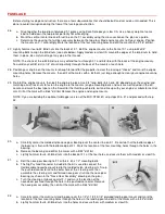
60.
Push the 1/4" dia. x1/2" long canopy hold-down dowel (left over from step 47a)
through the hole in CF1 until it extends just past the rear face of CF-2. Glue
around the dowel to CF-1, being careful not to get any glue on CF-2.
61.
a. Carefully trim or sand the edges of CF-1 for a perfect fit with the canopy.
You may have to remove the canopy base/CF-1 assembly several times
during this process, to avoid altering the shape of CF-2.
b. Remove the canopy base/CF-1 assembly from the airplane. Re-glue the
canopy hold-down dowel from the back side of CF-1. When dry, sand the
dowel off flush with the front face of CF-1.