


.
Aileron Control
205.
(Recall step 178.) Mount your aileron servo in plywood part ASM (aileron servo mount), which is already installed on the
bottom of the wing. REMEMBER: Do not over tighten the servo mounting screws to the point where they compress the
rubber grommets too far.
206.
Locate the Nylon Aileron Connectors and cut them apart. Thread one Nylon Aileron Connector onto the end of each
Aileron Torque Rod. Screw the connectors on until they are about 1/8" past the tip of the torque rods (see Plan Sheet 1,
Fuselage Side View).
207.
The aileron pushrods are made from two 10" Threaded Steel Rods. Screw a Nylon R/C Link halfway onto the threaded
end of each rod. Then clip the R/C Links into the holes in the Nylon Aileron Connectors and line up the pushrods with the
servo arms.
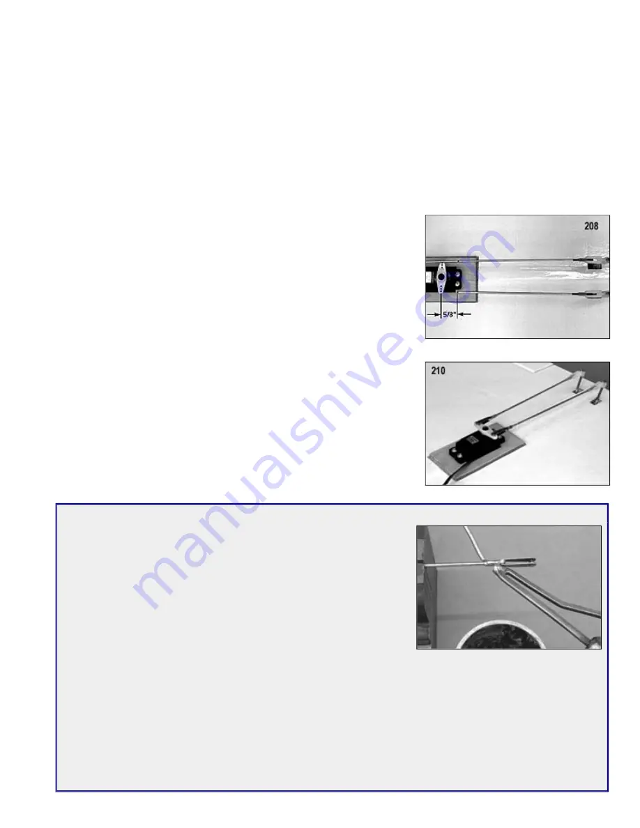
208.
Tape the ailerons in neutral position (the bottom of the ailerons and the wing
should be flush). Mark and cut the plain end of the pushrod wires 5/8" short of the
holes in the aileron servo arm.
209.
Solder an R/C Solder Link onto the end of each pushrod wire.
NOTE: It’s best to take the pushrods off for soldering. You wouldn’t want to drop
a piece of hot solder and burn a hole through the wing. Also, make sure the
pushrod wire sticks completely inside the barrel of the solder link.
210.
When done soldering, untape the ailerons and install the aileron pushrods
between the servo and the torque rods. It will probably be necessary to re-adjust
the overall length of the aileron pushrods, by screwing the Nylon R/C Links
further in or out, to get both ailerons into neutral position at the same time (make
sure the aileron servo is neutral while doing this).
211.
Temporarily plug the aileron servo into the receiver and test the operation of the
ailerons. If you sense any binding in the aileron movement, find the cause and fix
it now. With full right and left movement of the transmitter’s aileron control stick,
the ailerons should move approximately 3/8" up and 3/8" down.
NOTE: If you are not getting the correct amount of aileron travel, try moving the
nylon R/C links to a different hole in the servo arm. You can also screw the
Aileron Connectors up or down on the Torque Rods to increase or decrease the
amount of travel.
Why Solder Links
You may be wondering why we provided R/C Solder Links for the servo ends
of the aileron pushrods, when all the rest of the control system installation is
solderless! Why didn’t we use more Pushrod Connectors, or maybe just a "Z"
bend in the wire? Well first off, "Z" bends are a good alternative, but we felt
that they are too difficult for a beginner to make correctly on his first try.
Second, Pushrod Connectors are great, but not in all situations. They are
more than adequate for non-aerodynamic controls like the throttle and nose
gear. However the set screw in a Pushrod Connector can come loose! If that
happens to the throttle or nose gear, it most likely won’t cause any serious
problem. But if it happens to the ailerons, elevator, or rudder, the airplane will
most likely crash! That’s why you don’t see any Pushrod Connectors on the
ailerons, elevator, or rudder pushrods of the KADET LT-40!
If you have never soldered before, don’t worry, it’s not difficult. The hardest part will probably be coming up with a
soldering iron (or gun). If you don’t want to purchase one at this time, seek the assistance of someone who already has
one and knows how to use it. The secret to easy soldering is to use plenty of heat! You need a heavy-duty soldering iron
to do this job, not one of the little "pencil" style irons that are only intended for soldering small electrical wires and
components. It will take a soldering iron of at least 75 watts (100w or 200w is better) to solder the R/C Solder Links and
pushrod wires in this kit. Use ROSIN CORE SOLDER (60% tin, 40% lead) and a good brand of SOLDERING PASTE
FLUX. Put the wire in a vise. Coat the end of the wire with soldering paste flux. Slide on the R/C Solder Link. Press the
tip of the soldering iron firmly to the outside of the barrel of the R/C Solder Link. Let it heat! Keep the iron against the
barrel while you touch the tip of your solder to the joint (not to the soldering iron). When the two parts get hot enough,
the solder will melt and flow into the joint. Continue flowing solder into the joint until it is full. Let cool. Wipe the solder
joint clean with a rag.
Summary of Contents for KADET LT-40
Page 49: ... ...