Chapter 12
Universal Asynchronous
Receiver/Transmitter (UART)
This chapter describes the operation of the SiFive Universal Asynchronous Receiver/Transmitter
(UART).
UART Overview
The UART peripheral supports the following features:
•
8-N-1 and 8-N-2 formats: 8 data bits, no parity bit, 1 start bit, 1 or 2 stop bits
•
8-entry transmit and receive FIFO buffers with programmable watermark interrupts
•
16
×
Rx oversampling with 2/3 majority voting per bit
The UART peripheral does not support hardware flow control or other modem control signals, or
synchronous serial data tranfesrs.
Memory Map
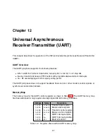
The memory map for the UART control registers is shown in Table 12.1. The UART memory map
has been designed to only require naturally aligned 32-bit memory accesses.
Address
Name
Description
0x000
txdata
Transmit data register
0x004
rxdata
Receive data register
0x008
txctrl
Transmit control register
0x00C
rxctrl
Receive control register
0x010
ie
UART interrupt enable
0x014
ip
UART Interrupt pending
0x018
div
Baud rate divisor
Table 12.1: Register offsets within UART memory map.
37
Summary of Contents for E300
Page 1: ...SiFive E300 Platform Reference Manual Version 1 0 1 c SiFive Inc ...
Page 2: ...2 SiFive E300 Platform Reference Manual Version 1 0 1 ...
Page 4: ...ii SiFive E300 Platform Reference Manual Version 1 0 1 ...
Page 12: ...4 SiFive E300 Platform Reference Manual Version 1 0 1 ...
Page 14: ...6 SiFive E300 Platform Reference Manual Version 1 0 1 ...
Page 22: ...14 SiFive E300 Platform Reference Manual Version 1 0 1 ...
Page 32: ...24 SiFive E300 Platform Reference Manual Version 1 0 1 ...
Page 40: ...32 SiFive E300 Platform Reference Manual Version 1 0 1 ...
Page 56: ...48 SiFive E300 Platform Reference Manual Version 1 0 1 ...
Page 60: ...52 SiFive E300 Platform Reference Manual Version 1 0 1 ...

