10
SiFive E300 Platform Reference Manual, Version 1.0.1
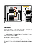
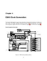
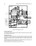
Figure 4.1 shows an overview of the E300 clock generation scheme. Most digital clocks on the
chip are divided down from a central high-frequency clock
hfclk
produced from either the PLL or
an on-chip trimmable oscillator. The PLL can be driven from either the on-chip oscillator or an off-
chip crystal oscillator. In systems without a PLL, the off-chip oscillator can drive the high-frequency
clock directly.
For the FE310-G000, the TileLink bus clock (
tlclk
) is fixed to be the same as the processor core
clock (
coreclk
). As shown, each peripheral may also generate local divided clocks from
tlclk
.
The Always-On block includes a real-time clock circuit that is driven from one of three possible
low-frequency clock sources: an off-chip 32 kHz crystal oscillator, an on-chip low-frequency RC
oscillator, or a clock divided down from
hfclk
.
Test mode can select the JTAG test clk (TCK) to be driven into all clock trees to support scan.
Internal Trimmable Programmable 72 MHz Oscillator (HFROSC)
An internal trimmable high-frequency ring oscillator (HFROSC) is used to provide the default clock
after reset, and can be used to allow operation without an external high-frequency crystal or a
PLL.
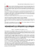
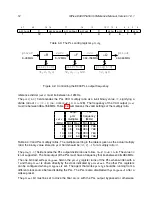
The oscillator is controlled by the
hfrosccfg
register, which is memory-mapped in the PRCI ad-
dress space, and whose format is shown in Figure 4.1.
31
30
29
21 20
16
15
6 5
0
hfroscrdy
hfroscen
0
hfrosctrim
0
hfroscdiv
1
1
9
5
10
6
Table 4.1: The HFROSC config register,
hfrosccfg
.
The frequency can be adjusted in software using a 5-bit trim value in the
hfrosctrim
. The trim
value (from 0–31) adjusts which tap of the variable delay chain is fed back to the start of the ring. A
value of 0 corresponds to the longest chain and slowest frequency, while higher values correspond
to shorter chains and therefore higher frequencies.
The HFROSC oscillator output frequency can be divided by an integer between 1 and 64 giving
a frequency range of 1.125 MHz–72 MHz assuming the trim value is set to give a 72 MHz output.
The value of the divider is given in the
hfroscdiv
field, where the divide ratio is one greater than
the binary value held in the field (i.e.,
hfroscdiv
=0 indicates divide by 1,
hfroscdiv
=1 indicates
divide by 2, etc.). The value of the divider can be changed at any time.
The HFROSC is the default clock source used for the system core at reset. After a reset, the
hfrosctrim
value is reset to 16, the middle of the adjustable range, and the divider is reset to
÷
5
(
hfroscdiv
=4), which gives a nominal 13.8 MHz (
±
50%) output frequency.
The value of
hfrosctrim
that most closely achieves an 72 MHz clock output at nominal conditions
(1.8 V at 25 C) is determined by manufacturing-time calibration and is stored in on-chip OTP stor-
age. Upon reset, software in the processor boot sequence can write the calibrated value into the
hfrosctrim
field, but the value can be altered at any time during operation including when the
processor is running from HFROSC.
Summary of Contents for E300
Page 1: ...SiFive E300 Platform Reference Manual Version 1 0 1 c SiFive Inc ...
Page 2: ...2 SiFive E300 Platform Reference Manual Version 1 0 1 ...
Page 4: ...ii SiFive E300 Platform Reference Manual Version 1 0 1 ...
Page 12: ...4 SiFive E300 Platform Reference Manual Version 1 0 1 ...
Page 14: ...6 SiFive E300 Platform Reference Manual Version 1 0 1 ...
Page 22: ...14 SiFive E300 Platform Reference Manual Version 1 0 1 ...
Page 32: ...24 SiFive E300 Platform Reference Manual Version 1 0 1 ...
Page 40: ...32 SiFive E300 Platform Reference Manual Version 1 0 1 ...
Page 56: ...48 SiFive E300 Platform Reference Manual Version 1 0 1 ...
Page 60: ...52 SiFive E300 Platform Reference Manual Version 1 0 1 ...


