background image

Installation

3-4

TIWAY 1 TI505 NIM User Manual

3.2

INSTALLING THE NIM

To place a NIM into your TI505 system, you have to select the NIM communication
parameters, install the NIM in the TI505 I/O base, connect the communication cables to
the NIM, and initialize the system for operation. The Programmable Controller (P/C)
and the programming device should be in place before you install a NIM.

WARNING

Do not insert or remove the NIM while power is applied
to the P/C system, since doing this may cause personal in-
jury, alter P/C memory, cause a P/C fatal error, or damage
the module.

The following steps summarize the NIM installation.

1.

Disconnect power to the P/C system (I/O base, power supply, etc.).

2.

Set the configuration dipswitches and LOCAL/REMOTE switch.

3.

Insert the module into the base and secure it with the bezel screws.

4.

Power up the P/C system.

5.

Use the NIM diagnostics and LED status indicators to be sure the module is op-
erating correctly.

6.

Use a programming device to verify that the NIM is logged into the P/C.

7.

Connect the network cables to the NIM.

The following paragraphs provide detailed information for each step.

Artisan Technology Group - Quality Instrumentation ... Guaranteed | (888) 88-SOURCE | www.artisantg.com

Summary of Contents for TIWAY I TI505

Page 1: ...xcess underutilized and idle equipment along with credit for buybacks and trade ins Custom engineering so your equipment works exactly as you specify Critical and expedited services Leasing Rentals Demos In stock Ready to ship TAR certified secure asset solutions Expert team I Trust guarantee I 100 satisfaction All trademarks brand names and brands appearing herein are the property of their respec...

Page 2: ... TI505 Network Interface Module User Manual Order Number PPX TIWAY 8124 2 Manual Assembly Number 2587871 0053 Second Edition Artisan Technology Group Quality Instrumentation Guaranteed 888 88 SOURCE www artisantg com ...

Page 3: ...ccess to data concerning all of the uses and applications of customer s products we do not assume responsibility either for customer product design or for any infringements of patents or rights of others which may result from our assistance Technical data is subject to change We check the contents of every manual for accuracy at the time it is approved for printing however there may be undetected ...

Page 4: ...IWAY 8124 2 Refer to this history in all correspondence and or discussion about this manual Event Date Description Original Issue 8 88 Original Issue 2601210 0001 Second Edition 3 94 Second Edition 2601210 0002 Artisan Technology Group Quality Instrumentation Guaranteed 888 88 SOURCE www artisantg com ...

Page 5: ...ctive Pages Second iii vii Second viii ix Second 1 1 1 6 Second 2 1 2 20 Second 3 1 3 21 Second 4 1 4 44 Second A 1 A 3 Second B 1 B 2 Second C 1 C 2 Second D 1 D 2 Second E 1 E 2 Second Registration Second Artisan Technology Group Quality Instrumentation Guaranteed 888 88 SOURCE www artisantg com ...

Page 6: ...INSTALLATION 2 6 2 3 1 Local Line Characteristics 2 6 2 3 2 Local Line Cable 2 8 2 3 3 Local Line Tap Housings 2 10 2 3 4 Planning Considerations 2 12 2 3 5 Local Line Tap Spacing 2 12 2 3 6 Cable Routing 2 14 2 3 7 Obstructions 2 15 2 4 LOCAL LINE BIASING 2 16 2 4 1 Biasing Configurations 2 16 2 4 2 Networks with only Self biased Devices 2 17 2 4 3 Networks with a Single Switch biased Device 2 17...

Page 7: ...ATS 4 12 4 7 DATA ELEMENT LOCATION RANGES 4 16 4 8 DATA FIELD LENGTH RESTRICTIONS 4 17 4 9 TI505 NIM PRIMITIVE DESCRIPTIONS 4 19 4 9 1 Exception Primitive Code 00 4 20 4 9 2 Native Primitive Code 01 4 22 4 9 3 Status Primitive Code 02 4 23 4 9 4 Configuration Primitive Code 03 4 24 4 9 5 Primitive Format Configuration Code 04 4 25 4 9 6 Packed Native Primitive Code 05 4 26 4 9 7 Change State Primi...

Page 8: ...N A 1 A 3 1 Networks with Switch biased Devices and CIMs A 2 A 3 2 Networks with Only Self biasing Devices and CIMs A 2 APPENDIX B NETWORK CONFIGURATION DATA SHEET B 1 APPENDIX C NETWORK EVALUATION FORM C 1 APPENDIX D SPECIFICATIONS D 1 APPENDIX E PRIMITIVE EXAMPLES E 1 Artisan Technology Group Quality Instrumentation Guaranteed 888 88 SOURCE www artisantg com ...

Page 9: ...mmary 3 6 3 3 Installing the NIM in the I O Base 3 13 3 4 NIM Switches 3 14 3 5 NIM Status Indicators 3 16 4 1 Basic Primitive Structure 4 3 4 2 Binary Weight of the Fields 4 4 4 3 Primitive Request and Response Field Format 4 8 4 4 Discrete Data Element Format 4 13 4 5 Packed Discrete Data Element Format 4 13 4 6 Forced Word Data Element Format 4 14 4 7 Forced Discrete and CR Data Element Format ...

Page 10: ...Logical Primitive Assignment 4 6 4 2 TI505 NIM Primitive Subset 4 7 4 3 Summary of Primitive Field Symbols 4 9 4 4 Data Element Types and Lengths 4 12 4 5 Data Element Location Ranges 4 16 4 6 Maximum Read Primitive Data Byte Length 4 17 4 7 Maximum Write Primitive Data Byte Length 4 18 4 8 Summary of Primitives 4 41 4 9 Summary of Primitives extended addressing 4 43 Artisan Technology Group Quali...

Page 11: ...network design configurations and the use of modems with TIWAY I Local Line cabling biasing and termination are also discussed CHAPTER 3 INSTALLATION describes NIM installation and diagnostic procedures CHAPTER 4 NIM PRIMITIVES describes NIM operation and the primitive subset supported by the NIM APPENDIX A SIMATIC PM550 CIM REQUIREMENTS contains procedures for Local Line biasing and termination f...

Page 12: ... assistance in contacting your distributor or sales office in the United States call 1 800 964 4114 Siemens Manual Number SIMATIC TIWAY I Host Adapter User Manual PPX TIWAY 8102 SIMATIC TIWAY I Host Software Programming Manual for DEC PDP 11 PPX TIWAY 8107 for TI and IBM Personal Computers PPX TIWAY 8108 for DEC VAX UNILINK PPX TIWAY 8123 PM550 Network Interface Module User Manual PPX 550 8110 SIM...

Page 13: ...e Local Line provides high noise immunity for networks up to 25 000 feet 7620 meters Throughout this manual the following networking terms are used HDLC TIWAY I High level Data Link Control data communications procedures with CRC 16 error checking and message length error checking Primary HDLC network manager TIWAY I Host Adapter TIWAY I Gateway or UNILINK Host Adapter with the Network Manager fun...

Page 14: ...ll or half duplex mode synchronously or asynchronously Both NRZ and NRZI data encoding are available 1 2 SYSTEM BLOCK DIAGRAM Figure 1Figure 1 illustrates the basic system block diagram of a TIWAY I Network System components include Host System Interfaces including Host Adapters Gateways and Network Control Modules Siemens Programmable Controller Network Interface Modules NIMs UNILINK Secondary Ad...

Page 15: ...Performing control operations on attached devices The Host issues requests Primitives to the NIMs and Secondary Adapters The secondaries then perform the requested operations on the attached devices and return the appropriate response to the Host to complete the transaction See Figure 1 Host Systems Host System Interfaces Command Initiators Siemens Programmable Controllers Secondary Adapters Non S...

Page 16: ...th a Jabberstop circuit to disable the port s transmitter in the event of a communication port failure This helps minimize failures resulting in continuous network transmission which would dominate the communication channel The NIM provides data integrity checking of network communications The NIM meets several stringent noise and environmental specifications Built in diagnostics aid in troublesho...

Page 17: ...423 drivers and receivers and operates at RS 423 A signal levels 5 or 5 volts These levels are also RS 232 C compatible The pin assignments for the RS 232 C port are given in Chapter 2 The Local Line interface is a differential line port for use with shielded twisted pair cable The Local Line interface provides line isolation and high noise immunity for installations up to 10 000 feet 25 000 feet ...

Page 18: ... munications NIM controller translates the communication between Primitives and the P C communication language Communications controller supervises data transactions between the NIM and the network host NETWORK INTERFACE MODULE SPECIAL FUNCTION INTERFACE CONTROLLER NIM CONTROLLER COMM CONTROLLER POWER MEDIA CIRCUITRY TO NETWORK COMM MEDIA Figure 2 NIM Simplified Block Diagram The basic difference ...

Page 19: ... Cs to a host computer The TI505 NIM provides the interface to the network host enabling the host and the P C to communicate with each other Also included with this manual is a TIWAY I Network Configuration Data Sheet Ap pendix B This will assist you in maintaining a complete up to date record of the config uration of your network which is especially important if you are using several different ty...

Page 20: ...short haul modem link ups cross plant or cross town coverage Siemens Local Line up to 25 000 feet NOTE TIWAY I does not directly support dial up modems which require Modem Control Commands for communication switchover This can be done but specific equipment is required to dial the remote number from the host device You can select from either type of media for the network but you cannot mix the typ...

Page 21: ... is supported for RS 232 C and Local Line NIMs This means you can have backup communication media in case of unforeseen cable problems or accidents In order to achieve true redundancy you must have completely redundant network media network trunk lines tap housings drop lines and modems For example if you need Local Line cable redundancy you will need one PPX 505 7339 TI505 NIM two separate twiste...

Page 22: ...tion 5 of EIA RS 232 C This interface uses a male plug 25 pin D type connector on the communica tion cable The circuits and pin assignments for the RS 232 C connector are shown in Table 3 Table 3 RS 232 C Connections Pin ISO RS 232 C Name Function 1 101 AA Protective Ground chassis 2 103 BA Transmitted Data 3 104 BB Received Data 4 105 CA Request to Send RTS 5 106 CB Clear to Send CTS 6 107 CC Dat...

Page 23: ...d time out feature is an important consideration when se lecting a TIWAY I compatible RF Modem Transmitter Receiver turn around time must be less than the one second network time out An additional half second delay from Clear to Send CTS to start of transmission can be added by setting the Keydelay Switch to the open position Chapter 3 provides addition al information concerning dipswitch settings...

Page 24: ...abling The Local Line cable may be up to 25 000 feet long depending on loading and baud rate selection It uses tap housings to simplify the addition of network connections The Local Line is designed to operate with shielded twisted pair cable which has a characteristic impedance of 124 ohms Taps and 9 pin connectors are supplied with the Local Line but extras may be necessary for cable splicing Su...

Page 25: ...4 Table 4 Pin Assignments for Local Line Connectors Pin Name Description 1 No connection 2 No connection 3 Shield Cable shield and signal common 4 No connection 5 No connection 6 LLM Positive biased signal line 7 No connection 8 No connection 9 LLM Negative biased signal line Artisan Technology Group Quality Instrumentation Guaranteed 888 88 SOURCE www artisantg com ...

Page 26: ...e type Tap length Tap spacing Number of secondaries Maximum baud rates Siemens recommends Belden 9860 twisted pair cabling or its equivalent for use as the Local Line network spine Belden 9271 or its equivalent should be used for the dropline Brands other than those listed here will be specified by Siemens on request CAUTION All local and national electrical codes and fire codes should be observed...

Page 27: ... number of units that may be at tached is shown horizontally Figure 1 Number of Local Line Secondaries versus Cable Length As shown in Figure 2Figure 1 when you use Belden 9860 cable or its equivalent up to 75 stations can be attached to a network operating at 38K bps and having a spine length of 20 000 feet At 115 2K bps the maximum length of a Local Line network having 254 stations is 10 000 fee...

Page 28: ...y without being rigidly mounted The tap housing not only allows an orderly connection to the TIWAY I network but also contains terminating resistors resists moisture relieves strain and provides noise isolation for attached cabling Tap housings are included for each Local Line port however extras may be ordered from your Applications Engineering Distributor or from Siemens Order PPX 500 5606 Figur...

Page 29: ...sistency in installation always connect the LLM Pin 6 of the Local Line Con nector to the white strand of the twisted pair and to the terminal marked W in the tap housing Connect the blue strand to the LLM Pin 9 of the Local Line Connector and to the terminal marked B in the tap housing The Cable Shield and Signal Common should be connected to Pin 3 of the Local Line connector and to terminal G in...

Page 30: ...isable one cable will very likely disable the second A detailed record of design and routing should be created and maintained This record should be complete enough to enable a user to trace and physically locate all cable paths and hardware components 2 3 5 Local Line Tap Spacing To calculate the minimum distance between tap nodes use the length of the dropline at the last tap node A tap node cons...

Page 31: ...Network Design Considerations 2 13 TIWAY 1 Ti505 NIM User Manual Figure 3 Tap Spacing Examples Artisan Technology Group Quality Instrumentation Guaranteed 888 88 SOURCE www artisantg com ...

Page 32: ...g building The following paragraphs describe some of the advantages and disadvantages of each type of cable routing 2 3 6 1 Under floor Routing For under floor routing the cable can be enclosed within ducts or with raised flooring in the open air Under floor systems enclosed in ducts are usually expensive and while they are better protected against unauthorized taps than are open air systems they ...

Page 33: ... require that network computing devices be positioned near a wall 2 3 7 Obstructions Aside from physical obstructions such as posts walls and partitions electrical interfer ence should also be avoided In general network cabling should never come into direct contact with any electrical con ductor and if cabling is installed inside a conduit the conduit should be grounded in ac cordance with applica...

Page 34: ...nterface devices used with the P Cs Possible combinations are Installations consisting solely of self biased devices Installations consisting of both switch biased and self biased devices Some older TIWAY I devices have Bias Switches Installations with PM550 CIMs This section covers self biased and switch biased configurations only All TI505 NIMs are self biasing Appendix A discusses biasing and t...

Page 35: ... the position on the line of the interface de vices does not matter 2 4 3 Networks with a Single Switch biased Device This configuration exists when only one TIWAY I Device on the Local Line has the Bias Switch and all other devices are self biasing The position of the switch biased device on the line does not matter but its Bias Switch must be on Artisan Technology Group Quality Instrumentation G...

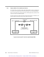
Page 36: ... attached place one at each end of the Local Line and turn on each Bias Switch All other devices having a Bias Switch can then be placed anywhere on the network with the Bias Switches turned off for the port being used See Figure 4 LOCAL LINE END OF LOCAL LINE END OF LOCAL LINE BIAS SWITCH OFF ON ALL OTHER SECONDARY DEVICES SWITCH BIASED NIM SWITCH BIASED NIM BIAS SWITCH ON BIAS SWITCH ON Figure 4...

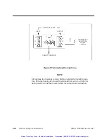
Page 37: ... the special case of a PM550 using a CIM as its interface to the net work see Appendix A for detailed line biasing and termination instruc tions which vary from those listed here Termination of the Local Line must be at the tap housings at the extreme ends of the net work spine and is accomplished as follows 1 The factory installed termination resistors in the tap housing see Figure 5 are left in ...

Page 38: ...s 5 1 4 WATT Figure 5 Terminating the Local Line NOTE All Siemens tap housings contain factory installed terminating resis tors If the tap housing is not used to terminate the Local Line the termi nating resistors must be removed when the output cable is attached Artisan Technology Group Quality Instrumentation Guaranteed 888 88 SOURCE www artisantg com ...

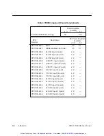
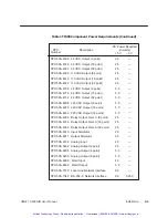
Page 39: ...I505 NIM contact your Siemens Industrial Automation Inc distributor or sales of fice for assistance If you need assistance in contacting your distributor or sales office in the United States call 1 800 964 4114 3 The communication configurations of all devices attached to the network must match i e they should each have the same data rate encoding etc 4 Calculate the I O base power budget to make ...

Page 40: ... Input 16 point 24 VAC Input 32 point LVDC TTL Input 8 point LVDC TTL Input 16 point LVDC TTL Input 32 point 110 VAC Input 8 point 110 VAC Input 16 point 110 VAC Input 32 point 2 0 PPX 505 4308 PPX 505 4316 PPX 505 4332 2 0 PPX 505 4408 2 0 PPX 505 4416 2 0 PPX 505 4432 2 0 2 0 2 0 PPX 505 4232 24 VDC Input 8 point 24 VDC Input 16 point 24 VDC Input 32 point 220 VAC Input 8 point 220 VAC Input 16 ...

Page 41: ... 505 4916 2 5 5 0 24 VDC Output 8 point 24 VDC Output 16 point 24 VDC Output 32 point 220 VAC Output 8 point 220 VAC Output 16 point 220 VAC Output 32 point Relay Output Form C 8 point Relay Output Form A 16 point Relay Output Form A 32 point 2 5 PPX 505 6010 PPX 505 6011 PPX 505 6108 4 0 PPX 505 6202 2 5 PPX 505 6204 5 0 PPX 505 6208 5 0 2 0 2 5 PPX 505 4932 Input Simulator Output Simulator Analo...

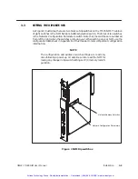
Page 42: ...jury alter P C memory cause a P C fatal error or damage the module The following steps summarize the NIM installation 1 Disconnect power to the P C system I O base power supply etc 2 Set the configuration dipswitches and LOCAL REMOTE switch 3 Insert the module into the base and secure it with the bezel screws 4 Power up the P C system 5 Use the NIM diagnostics and LED status indicators to be sure ...

Page 43: ...right when the switches are facing you When setting up your NIM use the configuration data sheet in Appendix B of this manual to record important configuration information NOTE The configuration and address switch settings are read only once following a power up or reset Be sure to reset the NIM fol lowing any change in dipswitch settings or P C memory reconfi guration Network Configuration Parame...

Page 44: ...ected Position Selected Push down to select 4 Network Configuration Parameters Network Address Selection Data Transmission Rate See Table 3 3 Synchronus Full duplex X 25 protocol NRZI encoding Lockout enabled Transmit delay active Transmit delay inactive Lockout disabled NRZ encoding HDLC protocol Half duplex Asynchronous 32 64 128 0 Communication Figure 2 Dipswitch Summary Artisan Technology Grou...

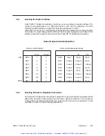
Page 45: ...dress Selection Table 3 2A Bit Weight Table 3 2B Address Examples Open Closed LSB SW8 SW7 SW6 SW5 SW4 SW3 SW2 SW1 MSB 1 2 4 8 16 32 64 128 0 0 0 0 0 0 0 0 1 25 203 Open Closed Closed Closed Closed Closed Closed Closed Open Open Closed Open Closed Closed Open Open Open Closed Closed Closed Closed Open Closed Open SW8 SW7 SW6 SW5 SW4 SW3 SW2 SW1 3 3 2 Selecting Network Configuration Parameters The N...

Page 46: ...tting switches one through four select a data rate which matches that of the modem exactly If this is not possible select the next lower data rate below that of the modems See the paragraph on Synchronous Asynchronous Selection Table 3 Network Data Rate Switch Settings SWITCH SETTINGS DATA RATE BPS SW1 SW2 SW3 SW4 0 0 0 0 110 0 0 0 1 110 0 0 1 0 110 0 0 1 1 110 0 1 0 0 110 0 1 0 1 150 0 1 1 0 300 ...

Page 47: ...elements are generated within the NIM Synchronous operation is not valid for Local Line operation When you use the Local Line medium this switch must be in the asynchronous position towards the top of the dips witch closed indicates asynchronous towards the bottom of the dipswitch open is syn chronous 3 3 2 3 Full Half Duplex Network Configuration Parameter switch 6 selects full or half duplex ope...

Page 48: ...itch 8 selects the method of data encoding used on the physical communication medium The NRZI method of data encoding provides a mechanism for the proper decoding of received data in an asynchronous communication environment In fact NRZ encoding will not work satisfactorily except in the case of synchronous RS 232 C communication When using Local Line or asynchronous RS 232 C NRZI encoding must be...

Page 49: ... before you can determine the lockout bit address See your P C manual for details on I O configuration 3 In your Relay Ladder Logic RLL program re enable NIM to P C com munication by turning the output off after the P C is able to resume com munication with the NIM 3 3 2 7 Transmit Delay or Keydelay Network Configuration Parameter switch 10 provides a delay of 500 milliseconds following the receip...

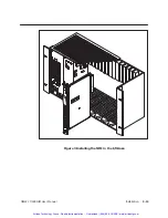
Page 50: ...all system power before re moving or installing I O modules Complete the following steps to install the module 1 Disconnect power to the P C system 2 Position the module so that the front bezel is facing you See Figure 3 3 Hold the top and bottom of the bezel and carefully slide the module into the slot pushing it all the way into the base If you have inserted the module correctly you will feel a ...

Page 51: ...Installation 3 13 TIWAY 1 Ti505 NIM User Manual Figure 3 Installing the NIM in the I O Base Artisan Technology Group Quality Instrumentation Guaranteed 888 88 SOURCE www artisantg com ...

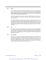
Page 52: ...e are three switches located under the hinged switch cover These switches which are shown in Figure 3Figure 4 are labeled RESET TEST and LOCAL REMOTE Figure 3Figure 4 NIM Switches Artisan Technology Group Quality Instrumentation Guaranteed 888 88 SOURCE www artisantg com ...

Page 53: ... Secondary Connect command If you remove the NIM from the base to change the configuration the NIM will automatically be reset when power is returned to the system 3 5 2 Test This switch will cause a series of diagnostic tests to be executed if the LOCAL REMOTE switch is in the LOCAL position Make sure you disconnect all communication cables and install loopback connectors part no 2641307 0001 on ...

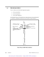
Page 54: ...stics The indicators located above the switch cover are shown in Figure 3Figure 5 NIM GOOD base power and NIM operation status PC GOOD P C NIM communication link status REC receiving data TEST test mode status XMT data transmit ON LINE connected to the TIWAY network Continuous on indicates remote mode flashing indicates local mode indicator indicator Figure 3Figure 5 NIM Status Indicators Artisan ...

Page 55: ...ll NIM LED indicators are turned on for approximately 1 second then all except the TEST indicator are turned off for approximately 10 seconds If the power up diagnostics are successful the NIM GOOD LED will be on and an attempt to establish communication with a TI505 P C will be made If this is successful the PC GOOD LED will illuminate and the NIM is ready for normal network operation If the powe...

Page 56: ... is on or flashing and fails to communicate with the P C it reports this to the host computer with an Exception Response Error Code 0A attached device failed to respond will be sent and the PC GOOD LED will be extinguished If communication is re established the NIM will return to Normal Response Mode and the PC GOOD LED will illuminate The Watchdog Timer circuit helps provide an extra measure of p...

Page 57: ...no 2641307 0001 on the NIM RS 232 C port s 3 Make certain the LOCAL REMOTE switch is in the Local position 4 Press the RESET switch 5 Press the TEST switch At the start of the diagnostics the TEST LED will be on with all other LED indicators off Then after approximately ten seconds all LED indicators will flash on and off for approximately two seconds When the diagnostics are finished the TEST LED...

Page 58: ...nector Following successful execution of the diagnostics the network cable s should be connected to the NIM the NIM Reset button should be pressed and the LOCAL REMOTE switch should be returned to the correct setting for your application This will reinitialize the NIM and it will return to normal operation If you need additional help or information that is not included in this Technical Advisory c...

Page 59: ...you can proceed with the usual operations If the line is blank or erroneous you should check the NIM to be sure it is firmly seated in the slot and enter the appropriate command again You can also use the PPX 505 7510 HIT Handheld Intelligent Terminal to verify that a module is operating correctly Just use the HIT to read the appropriate status word 11 18 for the base the module is installed in Se...

Page 60: ...rimitives provide a standard communication protocol that allow you to commu nicate with different types of Secondaries and attached devices without custom software routines Primitives allow more efficient use of the available network bandwidth by in creasing the amount of data that is available in a single message For example with a single programming peripheral Task Code P C communication lan gua...

Page 61: ...length and function type and location of data to be accessed and data to be transferred In TIWAY I a Primi tive forms the information field of an HDLC Information frame I or Unnumbered Infor mation frame UI if HDLC operation is selected If X 25 operation is selected the Primi tive is contained in the User Data field of an X 25 Data Packet WARNING When you write to memory you may be directly affect...

Page 62: ...t s Primitive Fields Request Format Response Format MSB LSB Length Prim Error Secondary Status Data Unit s Figure 1 Basic Primitive Structure The maximum length of the Information field is 273 bytes for the Series 505 NIM In the Request the 273 bytes include the Length Primitive code Descriptor and Data Unit fields In the Response the 273 bytes include the Length Primitive Code Error Secon dary St...

Page 63: ...d in the interpretation or execution of a Primitive The normal operation of a Primitive is for the initiating Host station to form a request Primitive and address it to a Secondary on the network If the request Primitive contains allowable descriptor and data unit fields a legal Primitive Code for the attached device and the correct Length Field value then the Secondary will return a response Prim...

Page 64: ...d and returns the reason for the exception The device requesting the Primitive should evaluate the message returned take appropriate cor rective measures and attempt to retransmit the Primitive 4 3 3 Exception When Writing When an Exception Primitive is returned in response to a Write Primitive P C write NIM block or record configuration change state etc you should verify that the actions were act...

Page 65: ...gories listed in Table 1 Table 1 Logical Primitive Assignment Function Primitive Code HEX 16 Bit Addressing Extended Addressing Exception and Status 00 0F 80 8F Control Read Write Program Modification Aids Data Acquisition Primitives Undefined Expansion 10 1F 20 2F 30 3F 40 4F 50 6F 70 7E 7F 90 9F A0 AF B0 BF C0 CF D0 EF F0 FE FF Artisan Technology Group Quality Instrumentation Guaranteed 888 88 S...

Page 66: ...nge state 20 A0 Read block single contiguous block 21 A1 Read random block 30 B0 Write block single contiguous block 31 B1 Write random block 50 D0 Define blocks up to 32 separate blocks 51 D1 Gather defined blocks 52 D2 Write and gather defined blocks 55 D5 Define records up to 32 records 56 D6 Gather defined records 57 D7 Write and gather defined records You can use extended addresses by adding ...

Page 67: ...is described in the following paragraphs Length Primitive Code Descriptor s Data Unit s Request Format Response Format Length Primitive Code Data Unit s Primitive Fields Error Response Format Length Exception Code Data Unit s Primitive Code Figure 3 Primitive Request and Response Field Format Artisan Technology Group Quality Instrumentation Guaranteed 888 88 SOURCE www artisantg com ...

Page 68: ...ngth field PP Primitive code HH Attached device status TT Data element types NNNN Number of data elements AAAA or AAAA AAAA Data element location DDDD Data unit s XX Number of user defined structures requested CC User defined structure number 4 5 2 Length Field LLLL The Length Field is a 16 bit field that represents the length in bytes of the Primitive Descriptor s and Data Unit field s The Length...

Page 69: ... contain a single descriptor or multiple descriptors as required by the various Primitives Data Element Type The length of the data element type descriptor field is eight bits This field labeled TT is a code that corresponds to the different types of data found in the attached device See Table 4Table 4 for a list of data element types Attached Device NIM Status The eight bit HH field designates th...

Page 70: ...values shown in Table 5 For TT Type 12 Drum Count Preset the format changes slightly The format of the AAAA field for this type is AAAA DD SS AAAA AAAA DDDD SSSS if using extended addressing where DD Drum Number SS Step Number 1 10 4 5 5 Basic Data Unit DDDD The definition of the Basic Data Unit Field is dependent upon the data element type spe cified in both the Descriptor Field and the Primitive...

Page 71: ...Memory V Constant Memory K Discrete Input X Discrete Output Y Control Register CR Discrete Input Packed X Discrete Output Packed Y Control Register Packed CR Word Input WX Word Output WY Timer Counter Preset TCP Timer Counter Current TCC Drum Step Preset DSP Drum Step Current DSC Drum Count Preset DCP Secondary System Status 0 1 2 3 4 5 6 7 8 9 A B C D E F 10 11 12 17 XY Force CR Force Word Force ...

Page 72: ... accessed First discrete bit number accessed Value Bit Definition 0 1 Off On If the number of packed discrete bits requested is not an even multiple of eight the unused positions are set to zero For example if you request 10 packed discrete input values the 6 least significant bits of the second byte of information will be set to zero Figure 5 Packed Discrete Data Element Format Artisan Technology...

Page 73: ...force a word but it will change the word value If used in a Write Primitive it can only write to an unforced Used only in Write Primitives to unforce a word It does not have a DDDD value and the data length is 1 byte instead of 3 bytes DDDD is the word value and is not used when MM FF Figure 6 Forced Word Data Element Format Artisan Technology Group Quality Instrumentation Guaranteed 888 88 SOURCE...

Page 74: ...and CR Data Element Format TT 17 Secondary System Status 2 words Word 1 Each bit set to 1 indicates that the corresponding bit in word 2 is a reported status Word 2 Status bits A B C This is a read only data type ABCD ABCD MSB LSB EFGH IJKL MNOP EFGH IJKL MNOP 0 NIM in REMOTE mode 1 NIM in LOCAL mode 0 P C System in REMOTE mode 1 P C System in LOCAL mode P undefined default to 0 Figure 8 Secondary...

Page 75: ... data element locations AAAA field for each data element type P C com bination are provided in Table 5 For all the ranges in the table the first legal value is 1 not zero Values of zero are not supported Artisan Technology Group Quality Instrumentation Guaranteed 888 88 SOURCE www artisantg com ...

Page 76: ... 1 8192 4096 0 1023 511 1023 1023 511 1023 256 30 1 12000 5120 0 1023 1023 1023 1023 1023 1023 400 30 1 4096 2048 0 1023 511 1023 1023 511 1023 256 30 1 12000 5120 0 1023 1023 1023 1023 1023 1023 400 30 1 Notes PPX 525 1102 1104 NOTE 1208 1212 PPX 535 1204 1212 P C Type A Entry of zero is non supported or non configured Data Type for the P C B There are 16 steps for each event drum in a P C The DC...

Page 77: ...hen using extended address 20 269 269 21 268 268 51 265 265 52 265 265 56 268 268 57 268 268 bytes read per Primitives requesting more than one data element type TT possible with Primitives 05 21 51 52 56 and 57 must be verified to contain a cumulative byte count of less than or equal to the byte counts in this table Consult Table 4 for the number of bytes per data element and Table 5 for data ele...

Page 78: ...k is requested Use one of the following formulas for the general case of one or more data block Normal addressing N 270 5 T Extended addressing N 270 7 T where N maximum number of bytes which may be written in this Primitive request T total number of writes specified in this Primitive request This number assumes that only one record is requested Use the following formula for the general case of on...

Page 79: ...5 NIM PRIMITIVE DESCRIPTIONS The following paragraphs describe the NIM Primitives used in the Series 505 NIM Refer to Table 2 for a complete list of the Primitives supported Artisan Technology Group Quality Instrumentation Guaranteed 888 88 SOURCE www artisantg com ...

Page 80: ...itive has insufficient data unit bytes 5 Number of information bytes received does not match the number of bytes specified in the field length 6 Attached device is in wrong mode for Primitive execution 7 User program in the attached device has disabled communication to the Series 505 NIM via the lock out bit A Attached device fails to respond E Primitive not valid for the specified data type TT 10...

Page 81: ...d with the attached device 1B Store and forward buffer is full and the store and forward message was discarded 1C Data element field specified by TT is improperly formatted 1D Number of locations to access equals zero NNNN 0 23 Number of data blocks defined in a data acquisition record exceeds the maximum supported 80DD Exception generated in the attached device is not identified TT Optional data ...

Page 82: ...itive 01 you can embed a P C unique Task Code and access anything in P C memory for example that a VPU can ac cess Request LLLL 01 DD DD where DDDD is the task code acceptable to the device be ing accessed Response LLLL 01 HH DD DD Symbol Value Definition HH Operational status see Status Primitive DDDD Defined by the attached device Artisan Technology Group Quality Instrumentation Guaranteed 888 8...

Page 83: ...erforming instruction data type execution with loop execution PROGRAM 03 Operational and not performing instruction data type or loop execution PROGRAM 04 Operational and not performing instruction data type execution with loop execution and a non fatal error is detected PROGRAM with non fatal error 05 Operational and not performing instruction and data type or loop execution and a non fatal error...

Page 84: ...30C TI535 0040 SIMATIC TI540 0050 SIMATIC TI550 0060 SIMATIC TI560 0065 SIMATIC TI565 007E SIMATIC UNILINK Host Adapter 0080 SIMATIC PM550 0081 SIMATIC PM551 0100 SIMATIC UNILINK Secondary Adapter 0200 IT 111 121 Intelligent Tank Transmitter 0204 IT 150 Hydrostatic Tank Transmitter 0208 IT 160 Micro Remote Control Unit EEEE hex Instruction data type memory size 4 bytes in extended FFFF hex Variabl...

Page 85: ...ition Records supported by the NIM For Primitives 55 56 and 57 32 is returned FF Number of Data Type Definitions supported in each defined record in the NIM For Primitives 55 56 and 57 32 is returned GG Floating Point Formats supported in the NIM 00 No floating point support 01 IBM Excess 64 format support 02 IEEE Standard 754 format support 03 Both IBM and IEEE format support BB 16 byte Primitive...

Page 86: ...he error results are returned in the packed native response in the same position as in a normal response Execution contin ues in this situation Native task codes concerning store and forward are not sup ported Request LLLL 05 CC DD DD repeated Response LLLL 05 HH CC DD DD repeated Symbol Value Definition HH Attached device operational status CC Number of bytes in the task code field DD DD Task cod...

Page 87: ... For an explanation of the modes of op eration for a specific P C refer to the manual for that particular pro grammable controller Request LLLL 10 DD where Symbol Value Definition DD Operational Status 00 Enter execution of instruction data type and execution of loops state RUN mode 01 Enter non execution of instruction data type and execution of loop states PROGRAM mode 02 Enter non execution of ...

Page 88: ...ll access contiguous data elements starting from a given data element location Request LLLL 20 TT NNNN AAAA Symbol Value Definition TT Data element type NNNN Number of locations AAAA Data element location Response LLLL 20 HH DD DD Symbol Value Definition HH Attached device operational status DD Data Artisan Technology Group Quality Instrumentation Guaranteed 888 88 SOURCE www artisantg com ...

Page 89: ...alue Definition TT Data element type NNNN Number of locations AAAA Data element location Response LLLL 21 HH XX BB DD DD repeated repeated XX times Symbol Value Definition HH Attached device operational status XX Number of blocks not processed due to error BB Block numbers not processed due to error This field only contains a value when the P C is reporting a P C error DD Data requested Artisan Te...

Page 90: ...data starting from a given data element location with the data specified in the request Request LLLL 30 TT AAAA DD DD Symbol Value Definition TT Data element type AAAA Data element location DD Data Response LLLL 30 HH Symbol Value Definition HH Attached device operational status Artisan Technology Group Quality Instrumentation Guaranteed 888 88 SOURCE www artisantg com ...

Page 91: ...DD Data Response LLLL 31 HH XX BB BB BB is repeated XX times Symbol Value Definition HH Attached device operational status XX Number of block writes not completed due to error BB Block numbers not processed due to error with the first block in the sequence referenced as block 1 CAUTION Blocks in error specified by BB may have been partially written before a failure occurred Valid blocks will compl...

Page 92: ...Define Block Primitive to re define the data acquisition blocks 4 9 12 1 Define Block Primitive Code 50 The Define Block Primitive specifies up to 32 random blocks of data elements See Table 4Table 5 for the allowable data element location ranges The blocks are referenced by number ranging from 1 to 20 hex A block once defined can be re defined to a different data element type and location by simp...

Page 93: ...s beginning with the lowest block number and increasing to the highest block number A data block separator is not provided in the response Request LLLL 51 EEEEEEEE where EEEEEEEE is 32 bits defined as Block Number 1 hex Block Number 20 hex MSB LSB Response LLLL 51 HH EEEEEEEE DD DD repeated Symbol Value Definition HH Attached device operational status EEEEEEEE EEEEEEEE is a mask as defined by the ...

Page 94: ...rimi tive a bit value of 1 indicates that the block is to be returned A bit value of 0 means that the block will not be returned You should not request more data than can be returned in a maximum length Primitive frame Following the mask are the descriptors associated with the write function which is performed before the gather operation The response will return the data associated with the reques...

Page 95: ...inition HH Attached device operational status EEEEEEEE EEEEEEEE is a mask as defined by the Request Primitive DD Data defined by the block being read The order of return of the blocks is from the lowest numbered block to the highest For example if blocks 2 4 and A were requested the first data block in the response specifies data which is associated with block 2 the next data block specifies data ...

Page 96: ...itive 56 collects the data blocks for the requested records The Write and Gather Record Primitive 57 combines the func tions of the Write Block Primitive 30 and the Gather Record Primitive 56 NOTE The record definitions are destroyed in the event of a power loss or a hardware reset or HDLC DISC command Any initialization or re init ialization procedures must use the Define Record Primitive 55 to r...

Page 97: ...peated DD times repeated for each record Symbol Value Definition CC Number assigned to the record The allowable range is 1 to 20 HEX DD Number of data type definitions blocks for the record TT Data element type NNNN Number of locations AAAA Data element location The total byte count of data elements defined by the record s must not cause the gather record response to exceed the maximum Primitive f...

Page 98: ...ords in the same order as they were requested A data record or data type separator is not provided in the Response Primitive NOTE Data will not be returned for records in error Invalid records will cause a Primitive error Request LLLL 56 XX CC CC is repeated XX times Symbol Value Definition XX Number of records requested CC Record numbers requested Response LLLL 56 HH XX CC DD DD repeated repeated...

Page 99: ...eed the max imum frame length Following the record numbers are the descriptors associated with the write function The write function is performed before the gather operation The response returns the data associated with the requested records by starting with the lowest number record and in creasing to the highest record A data record or data type separator is not provided in the response NOTE An e...

Page 100: ...ocation to write DD Data to write Maximum DD ranges may vary depending on the number of records specified for the read function Response LLLL 57 HH XX CC DD DD repeated XX times repeated Symbol Value Definition HH Attached device operational status XX Number of records in error CC Record numbers in error DD Data records returned without errors Artisan Technology Group Quality Instrumentation Guara...

Page 101: ...Response Request Response Request Response Request Response Request Response None LLLL 00 PP DDDD TT LLLL 01 DD DD LLLL 01 HH DD DD LLLL 02 LLLL 02 HH EE FF LLLL 03 LLLL 03 HH DDDD EEEE FFFF GGGG IIII JJJJ KKKK KKKK LLLL 04 LLLL 04 NNNN MM EE FF GG BB BB LLLL 05 CC DD DD LLLL 05 HH CC DD DD LLLL 10 DD LLLL 10 HH LLLL 20 TT NNNN AAAA LLLL 20 HH DD DD LLLL 21 TT NNNN AAAA LLLL 21 HH XX BB DD DD LLLL...

Page 102: ...uest Response Request LLLL 51 EEEEEEEE LLLL 51 HH EEEEEEEE DD DD LLLL 52 EEEEEEEE TT AAAA DD DD LLLL 52 HH EEEEEEEE DD DD LLLL 55 CC DD TT NNNN AAAA LLLL 55 HH LLLL 56 XX CC CC is repeated XX times repeated Blocks repeated repeated DD times repeated up to 32 times Response LLLL 56 HH XX CC DD DD repeated XX times repeated Write and Gather Request LLLL 57 XX CC TT AAAA DD DD Response LLLL 57 HH XX ...

Page 103: ...nse Request Response Request Response Request Response Request Response None LLLL 00 PP DDDD TT LLLL 81 DD DD LLLL 81 HH DD DD LLLL 82 LLLL 82 HH EE FF LLLL 83 LLLL 83 HH DDDD EEEE EEEE FFFF FFFF GGGG GGGG IIII IIII LLLL 84 LLLL 84 NNNN MM EE FF GG BB BB LLLL 85 CC DD DD LLLL 85 HH CC DD DD LLLL 90 DD LLLL 90 HH LLLL A0 TT NNNN AAAAAAAA LLLL A0 HH DD DD LLLL A1 TT NNNN AAAA AAAA LLLL A1 HH XX BB D...

Page 104: ...quest Response Request Response Request LLLL D1 EEEEEEEE LLLL D1 HH EEEEEEEE DD DD LLLL D2 EEEEEEEE TT AAAAAAAA DD DD LLLL D2 HH EEEEEEEE DD DD LLLL D5 CC DD TT NNNN AAAAAAAA LLLL D5 HH LLLL D6 XX CC repeated XX times repeated Blocks repeated repeated DD times repeated up to 32 times Response LLLL D6 HH XX CC DD DD repeated XX times repeated Write and Gather Request LLLL D7 XX CC TT AAAAAAAA DD DD...

Page 105: ...tion However in networks containing the PM550 CIM the Local Line length is restricted to 10 000 feet and 9600 baud A 3 LOCAL LINE BIAS AND TERMINATION For TIWAY I networks using the Local Line some devices are provided with a toggle switch to allow selection of bias or no bias for the Local Line Other devices have self biasing built in and therefore have no bias switch The CIM is provided with a j...

Page 106: ...ocal Line by the CIM To accomplish this proceed as follows 1 On networks having only one CIM place this CIM at one end of the Local Line trunk and install the jumpers provided with the CIM in accordance with the instructions in the PM550 CIM User s Manual Manual Number PM550 1101154 4 This will apply the correct bias to the Local Line to prevent oscillations of the CIM receivers To terminate the L...

Page 107: ...50 ohms in each instance and the connection is in accordance with instructions inside the tap housing The combination of termination resistors in the CIM together with these 150 ohm resistors provides the correct Local Line termination The following block diagram Figure A 1 illustrates the proper placement of the CIMs and the termination resistors for networks having CIMs and NIMs without the bias...

Page 108: ... Media type Sync Asynch Encoding Node Name Controller Type GENERAL SPECIFICATIONS NETWORK NODE SPECIFICATIONS Serial Number Software Release Interface Type Serial Number Software Release Location Network Baud Rate Full Half Duplex Modem Type Network Address Artisan Technology Group Quality Instrumentation Guaranteed 888 88 SOURCE www artisantg com ...

Page 109: ... TI505 NIM User Manual Date Name or Identifier DATA DEFINITION TABLE Data Type Starting Address Number of Elements Record Number Block Number Length Bytes Artisan Technology Group Quality Instrumentation Guaranteed 888 88 SOURCE www artisantg com ...

Page 110: ...Network Configuration Data Sheet B 3 TIWAY 1 TI505 NIM User Manual Artisan Technology Group Quality Instrumentation Guaranteed 888 88 SOURCE www artisantg com ...

Page 111: ...omation Inc to evaluate your network requirements complete and submit the Network Evaluation Form Seimens Industrial Automation Inc s Technical Services group will analyze your requirements and provide you with a network design plan and quote Artisan Technology Group Quality Instrumentation Guaranteed 888 88 SOURCE www artisantg com ...

Page 112: ...ORKS OR DEVICES WHO WILL BE WRITING THE APPLICATION SOFTWARE SPECIAL SAFETY REQUIREMENTS LIST ELECTRICAL NOISE PROBLEMS OTHER REQUIREMENTS OR NOTES WHEN DOES THE NETWORK HAVE TO BE OPERATIONAL WHEN DOES THE COMPLETE SYSTEM HAVE TO BE OPERATIONAL WHO DEFINES THE PLC CONTROL ENVIRONMENT NAME __________________________________________________ PHONE ______ __________ WHO DEFINES THE NETWORK AND SYSTEM...

Page 113: ...tes axis Impact Shock IEC 68 2 27 Test Ea Half Sine 15g 11ms Electrostatic Discharge IEC 801 Part 2 Level 4 15 kV Noise Immunity Conducted IEC 801 Part 4 Level 3 MIL STD 461B Part 4 CS01 CS02 CS06 IEC 255 4 Appendix E EEC 4517 79 Com 78 766 Final Part 4 IEC 472 2 5 kV Noise Immunity Radiated IEC 801 Part 3 Level 3 MIL STD 461B Part 4 RS01 RS02 Corrosion Protection All parts are of corrosion resist...

Page 114: ... ADCCP UN 4 class of procedure per Chapter 11 of ANSI Standard X3 66 1979 The Series 505 NIM operates as an HDLC Secondary station on the network Network Control Protocol TIWAY I normally operates with null network layer services however the user may optionally select CCITT X 25 protocol in the Permanent Virtual Circuit Mode of operation Network Media Shielded twisted pair cable for Local Line or ...

Page 115: ... AAAA 0006 20 01 0004 0064 where LLLL Length 0006 Primitive Code 20 TT Data Type 01 V variable memory NNNN Number of locations 0004 AAAA Address data element location 0064 Response LLLL 20 HH DD DD 000A 20 00 8464 8665 A001 01F4 LLLL Length 000A Primitive Code 20 HH Status 00 unit operational and executing logic DDDD values read from V memory V0100 8464 V0101 8665 V0102 A001 V0103 01F4 Artisan Tec...

Page 116: ...s format for Primitive 20 TT Data Type 01 V variable memory NNNN Number of locations 0004 AAAA AAAA Address 0000 0064 Response LLLL A0 HH DD DD 000A A0 00 8464 8665 A001 01F4 LLLL Length 000A Primitive Code A0 extended address format for Primitive 20 HH Status 00 unit operational and executing logic DDDD values read from V memory V100 8464 V101 8665 V102 A001 V103 01F4 Artisan Technology Group Qua...

Page 117: ...I530 TI530C TI535 TI540 TI550 TI560 TI565 are trademarks of Texas Instruments Incorporated DEC PDP and VAX are trademarks of Digital Equipment Corporation Belden is a registered trademark of Cooper Industries IBM is a registered trademark of International Business Machines Corporation Artisan Technology Group Quality Instrumentation Guaranteed 888 88 SOURCE www artisantg com ...

Page 118: ...ze Index Would you be interested in giving us more detailed comments about our manuals Yes Please send me a questionnaire No Thanks anyway Your Name Title Telephone Number Company Name Company Address Manual Name SIMATIC TWAY 1 TI505 Network Interface User Manual Edition Second Manual Assembly Number 2587871 0053 Date 03 94 Order Number PPX TIWAY 8124 2 Artisan Technology Group Quality Instrumenta...

Page 119: ... BY ADDRESSEE NO POSTAGE NECESSARY IF MAILED IN THE UNITED STATES ATTN Technical Communications M S 3519 SIEMENS INDUSTRIAL AUTOMATION INC 3000 BILL GARLAND RD P O BOX 1255 JOHNSON CITY TN 37605 1255 Artisan Technology Group Quality Instrumentation Guaranteed 888 88 SOURCE www artisantg com ...

Page 120: ...quipment Have surplus equipment taking up shelf space We ll give it a new home Learn more Visit us at artisantg com for more info on price quotes drivers technical specifications manuals and documentation Artisan Scientific Corporation dba Artisan Technology Group is not an affiliate representative or authorized distributor for any manufacturer listed herein We re here to make your life easier How...

Reviews: