


05.91
9 Axis/PLC Interface (DB 32)
9.2 Signals from axis
Rotary and linear measuring systems
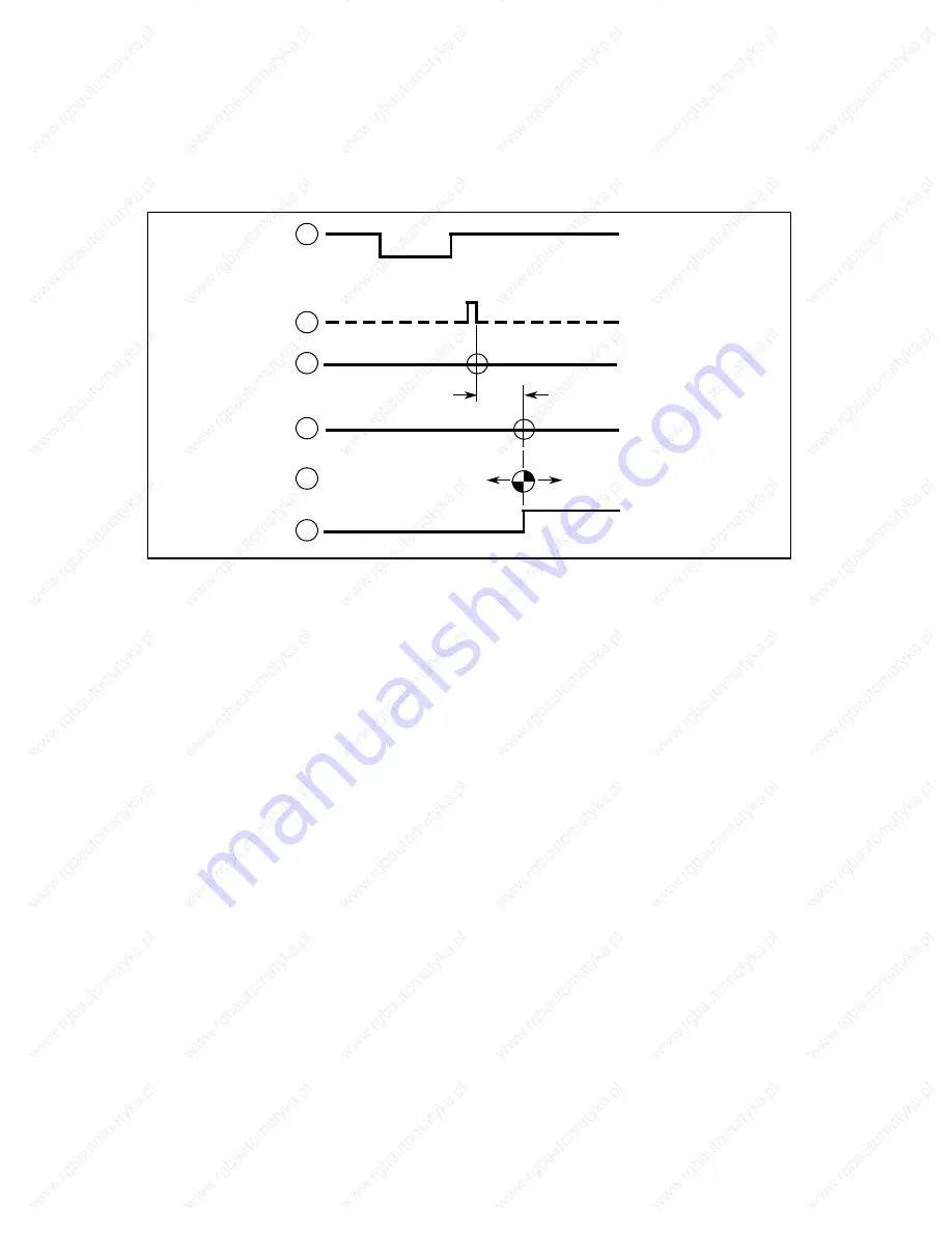
The reference point can be shifted by means of the "reference point shift" machine data in the
range ± 9999 units, referred to the 2000 units point (MD 244*). After reaching the reference
point position, the actual value memory of the axis is set to the reference point value (specified
in machine data MD 240*) and the REFERENCE POINT REACHED signal is output.
2000 units
± 9999 units
1
2
3
4
5
6
1: *DECELERATION signal
2: Measuring system zero mark signal
3: Measuring system zero mark
4: Zero mark plus 2000 units travel in the reference point approach direction
5: Reference point in the range: zero mark plus (2000 units ± 9999 units ref. point shift)
6: REFERENCE POINT REACHED signal
See the Function Manual "Extended Spindle Functions" for notes on reference point approach
of the spindle in C-axis mode.
Linear scales with distance-coded reference marks
d)
Linear scales with distance-coded reference marks have not only an incremental track but also
a reference mark track. The absolute position of the axis is determined by travelling over two
reference marks from any position in either direction and the signal REFERENCE POINT
REACHED is set.
_______
d)
with GA2, software version 1 and higher
©
Siemens AG 1991 All Rights Reserved 6ZB5 410-0HE02
9
–
3
SINUMERIK 880 (PJ)


