


Installing/mounting
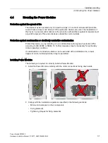
4.4 Mounting the Power Modules
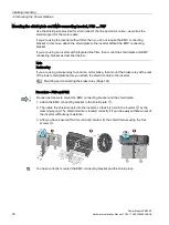
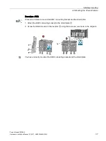
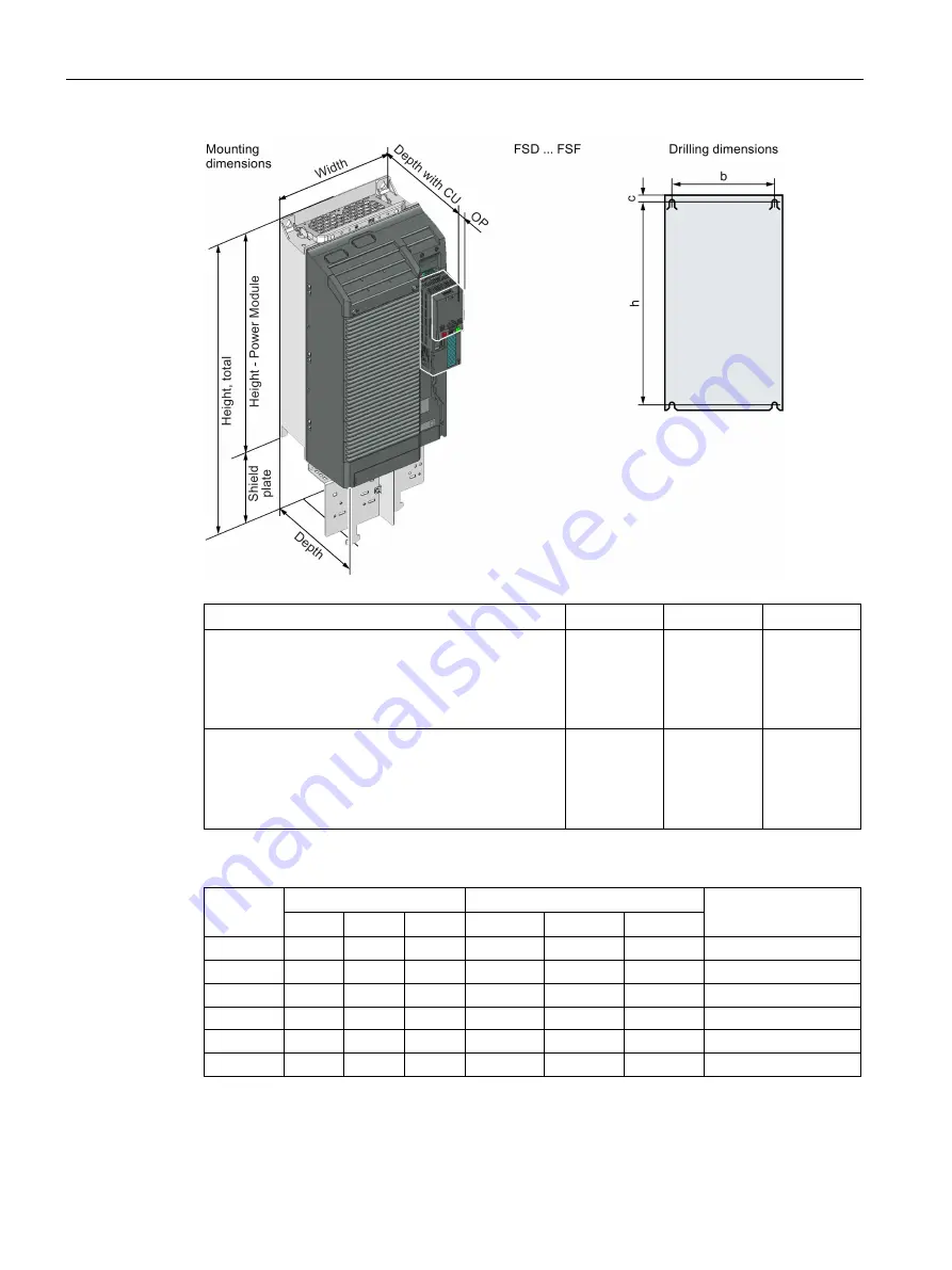
Power Module PM240-2
34
Hardware Installation Manual, 01/2017, A5E33294624B AE
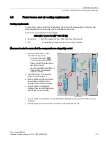
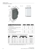
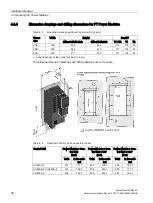
Depth with Control Unit and Operator Panel (mm)
CU230P-2
CU240B/E-2
CU250S-2
FSA … FSC
•
With Control Unit:
•
With Control Unit and blanking cover / BOP-2:
•
With Control Unit and IOP:
+ 59
+ 70
+ 81
+ 41
+ 52
+ 63
+ 62
+ 73
+ 84
FSD … FSF
•
With Control Unit:
•
With Control Unit and blanking cover / BOP-2:
•
With Control Unit and IOP:
+ 15.5
+ 26.5
+ 37.5
+ 0
+ 8.5
+ 19.5
+ 18.5
+ 29.5
+ 40.5
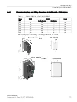
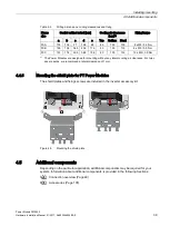
Table 4- 2
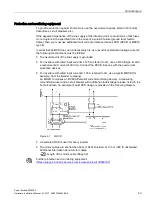
Drilling dimensions, cooling air clearances [mm] and fixing [Nm]
Frame
size
Drilling dimensions
Cooling air clearances
1)
Fixing/torque
h
b
c
Top
Bottom
Front
FSA
186
62.3
6
80
100
100
3 x M4 / 2.5
FSB
281
80
6
80
100
100
4 x M4 / 2.5
FSC
343
120
6
80
100
100
4 x M5 / 3.5
FSD
430
170
7
300
350
100
4 x M5 / 6.0
FSE
509
230
8.5
300
350
100
4 x M6 / 10
FSF
680
270
13
300
350
100
4 x M8 / 25
1)
The Power Modules are designed for mounting without any lateral cooling air clearance. For toler-
ance reasons, we recommend a lateral clearance of approx. 1 mm.
Summary of Contents for SINAMICS PM240-2
Page 1: ......
Page 2: ......
Page 8: ...Table of contents Power Module PM240 2 8 Hardware Installation Manual 01 2017 A5E33294624B AE ...
Page 104: ...Spare parts Power Module PM240 2 104 Hardware Installation Manual 01 2017 A5E33294624B AE ...
Page 143: ......
Page 144: ......