Installing/mounting
4.2 EMC-compliant installation of a machine or system
Power Module PM240-2
Hardware Installation Manual, 01/2017, A5E33294624B AE
27
Routing cables outside the control cabinet
●
Maintain a minimum clearance of 25 cm between cables with a high level of interference
and cables with a low level of interference.
●
Using shielded cables for the following connections:
–
Inverter motor cable
–
Cable between the inverter and braking resistor
–
Signal and data cables
●
Connect the motor cable shield to the motor enclosure using a PG gland that establishes
a good electrical connection.
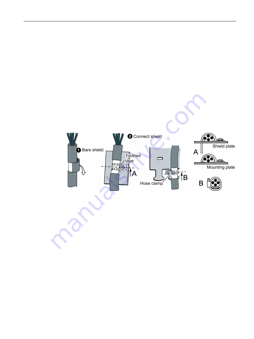
Requirements relating to shielded cables
●
Use cables with finely-stranded, braided shields.
●
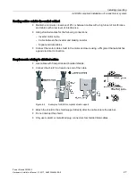
Connect the shield to at least one end of the cable.
Figure 4-4
Examples for EMC-compliant shield support
●
Attach the shield to the shield support directly after the cable enters the cabinet.
●
Do not interrupt the shield.
●
Only use metallic or metallized plug connectors for shielded data cables.
Summary of Contents for SINAMICS PM240-2
Page 1: ......
Page 2: ......
Page 8: ...Table of contents Power Module PM240 2 8 Hardware Installation Manual 01 2017 A5E33294624B AE ...
Page 104: ...Spare parts Power Module PM240 2 104 Hardware Installation Manual 01 2017 A5E33294624B AE ...
Page 143: ......
Page 144: ......


