


Installing/mounting
4.2 EMC-compliant installation of a machine or system
Power Module PM240-2
Hardware Installation Manual, 01/2017, A5E33294624B AE
25
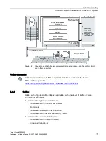
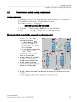
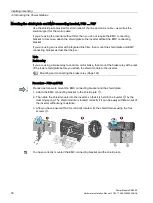
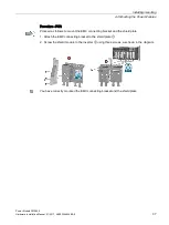
Figure 4-2
Grounding and high-frequency equipotential bonding measures in the control cabinet
and in the plant/system
Further information
Additional information about EMC-compliant installation is available in the Internet:
EMC installation guideline
https://support.industry.siemens.com/cs/ww/de/view/60612658/en
4.2.2
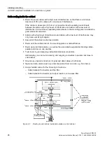
Cables
Cables with a high level of interference and cables with a low level of interference are
connected to the inverter:
●
Cables with a high level of interference:
–
Cable between the line filter and inverter
–
Motor cable
–
Cable at the inverter DC link connection
–
Cable between the inverter and braking resistor
●
Cables with a low level of interference:
–
Cable between the line and line filter
–
Signal and data cables
Summary of Contents for SINAMICS PM240-2
Page 1: ......
Page 2: ......
Page 8: ...Table of contents Power Module PM240 2 8 Hardware Installation Manual 01 2017 A5E33294624B AE ...
Page 104: ...Spare parts Power Module PM240 2 104 Hardware Installation Manual 01 2017 A5E33294624B AE ...
Page 143: ......
Page 144: ......