


Connecting
4.2 Connecting the converter to the device
SINAMICS CONNECT
Operating Instructions, 10/2018, A5E45421408
33
Note
The length of the Ethernet cable must be less than 30 m or the communication will be
unstable.
4.1.5
Securing the cables
Use cable ties or cable clamps to secure the connected cables to suitable fixing elements for
strain relief.
Make sure that the cables are not crushed by the cable tie or the cable clamps.
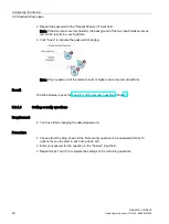
4.2
Connecting the converter to the device
4.2.1
Connecting the converter
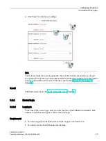
Connect the converter to interface X121 (ports 1 to 4) or X122 (ports 5 to 8) of the device.
Each port has four terminals (TX
n
, RX
n
, M, PE
n
; n = port number).
You can connect one SINAMICS CONNECT device to one or more (maximum eight) of the
following converters via the RS232 interface on the converter specific optional module or
Control Unit:
●
SINAMICS V20
●
SINAMICS G120 series (G120D excluded)
●
MICROMASTER 440
Interface assignment (converter side)
Module
RS232 interface on
the module
Pin No.
Signal name
Description
BOP Interface Module
for SINAMICS V20
1
RXD
Receive data
2
TXD
Transmit data
3
GND
Signal ground
Control Unit for
SINAMICS G120 series
(G120D excluded)
2
RXD
Receive data
3
TXD
Transmit data
5
GND
Signal ground
PC converter connector
module for
MICROMASTER 440
2
RXD
Receive data
3
TXD
Transmit data
5
GND
Signal ground