background image

Connecting 


4.1 Connecting the device 


SINAMICS CONNECT 

32


Operating Instructions, 10/2018, A5E45421408 

4.1.3


Connecting the device to MindSphere network 

Connect the device to the MindSphere network via interface X1. 


Interface 

IP address 

Description 

X1 

DHCP address 

RJ45 Ethernet connection 2 for 10/100 Mbps. Access to the Inter-

net (to MindSphere). 
Required to get connected to MindSphere. 

Procedure 

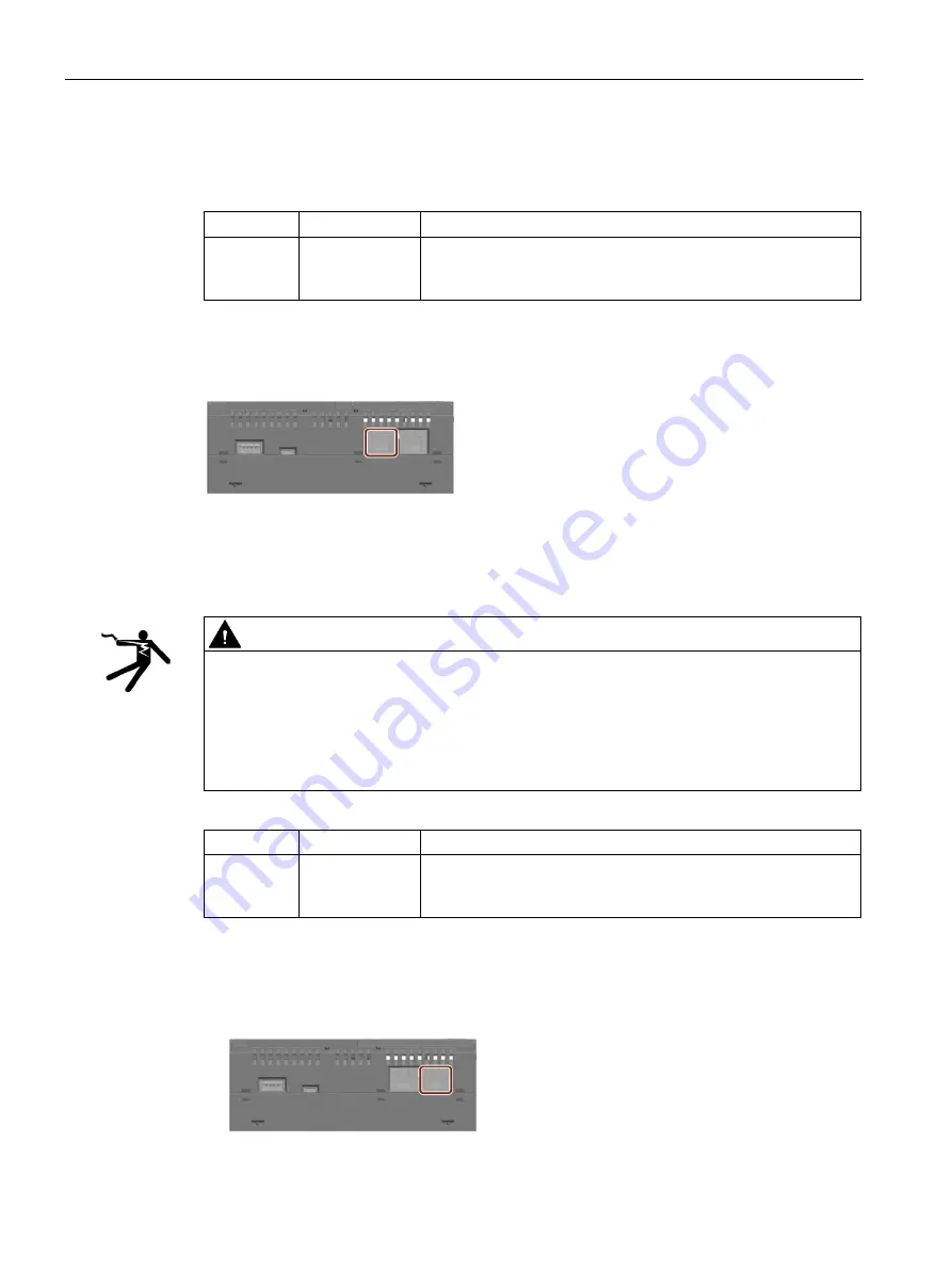
Insert the Ethernet cable for Internet into the port labeled with X1 P1 on the device. 


4.1.4


Connecting the device to a PC 

Connect the device to a PC via interface X2. 


WARNING 

Safety notice for connections with the LAN X2 connector 
Improper connection might cause high voltages. The LAN X2 connector is designed for 

connection to a Local Area Network “Environment A” according to IEEE802.3 or 

"Environment 0" according to IEC TR 62102 only.  


Do not connect the LAN X2 connector directly to the telephone network or a WAN (Wide 

Area Network). 


Interface 

IP address 

Description 

X2 

Static IP address  RJ45 Ethernet connection 1 for 10/100 Mbps. Access to the plant 

network (to PC). 
Required to configure the SINAMICS CONNECT.  

Procedure 

1.


Insert one end of the Ethernet cable to an Ethernet port of the PC. 

2.


Insert the other end of the Ethernet cable to the port labeled with X2 P1 on the device. 


Summary of Contents for Sinamics Connect Series

Page 1: ......

Page 2: ......

Page 3: ...__________________ ___________________ ___________________ SINAMICS SINAMICS CONNECT Operating Instructions Software 1 0 0 10 2018 A5E45421408 Preface Safety instructions 1 Overview 2 Mounting 3 Connecting 4 Configuring the device 5 Getting connected to MindSphere 6 Maintaining and repairing the device 7 Technical specifications 8 Appendix A ...

Page 4: ...y by personnel qualified for the specific task in accordance with the relevant documentation in particular its warning notices and safety instructions Qualified personnel are those who based on their training and experience are capable of identifying risks and avoiding potential hazards when working with these products systems Proper use of Siemens products Note the following WARNING Siemens produ...

Page 5: ...ice documentation comprises SINAMICS CONNECT Operating Instructions SINAMICS CONNECT Quick Install Guide Conventions The term device refers to a SINAMICS CONNECT unit Figures This manual contains figures of the described devices The supplied devices may differ in some details from the figures Within some of the figures one device is used to represent all devices Reference You can find the overview...

Page 6: ...ility of these third party products You can use equivalent products from other manufacturers Siemens does not accept any warranty for the properties of third party products Compliance with the General Data Protection Regulation Siemens respects the principles of data protection in particular the data minimization rules privacy by design For this product this means The product does not process neit...

Page 7: ...ce 19 2 3 Scope of delivery 20 2 4 Accessories 22 3 Mounting 23 3 1 Preparing for installation 23 3 1 1 Checking the delivery 23 3 1 2 Permitted mounting orientation and mounting types 24 3 2 Mounting the device 25 3 2 1 Mounting instructions 26 3 2 2 Mounting on DIN rails 27 3 2 3 Wall mounting 27 4 Connecting 29 4 1 Connecting the device 29 4 1 1 Notes on connecting 29 4 1 2 Connecting the power...

Page 8: ...ing time 57 5 2 7 Account related settings 59 5 2 7 1 Changing the password 59 5 2 7 2 Changing security questions 59 5 2 7 3 Logging out 60 6 Getting connected to MindSphere 61 6 1 Overview 61 6 2 Logging in to MindSphere 61 6 3 Creating an asset in Asset Manager 62 6 3 1 Creating aspects and variables 62 6 3 2 Creating a type 66 6 3 3 Creating an asset 69 6 4 Transferring configuration to the de...

Page 9: ... 8 4 3 Power demand of the components 87 8 4 4 Direct current power supply DC 87 8 4 5 Address of CE authorized manufacturer 88 8 5 Hardware description 88 8 5 1 Interface overview 88 8 5 2 Power supply 89 8 5 3 Ethernet interface 89 8 5 4 RS232 interface 90 A Appendix 91 A 1 Assembly of cable terminals on the device side 91 A 2 Technical support 93 Glossary 94 Index 96 ...

Page 10: ...ary supply circuits are de energized 6 Ensure that the motors cannot move 7 Identify all other dangerous energy sources e g compressed air hydraulic systems or water Switch the energy sources to a safe state 8 Check that the correct drive system is completely locked After you have completed the work restore the operational readiness in the inverse sequence WARNING Risk of electric shock and fire f...

Page 11: ...ations WARNING Electric shock due to connection to an unsuitable power supply When equipment is connected to an unsuitable power supply exposed components may carry a hazardous voltage that might result in serious injury or death Only use power supplies that provide SELV Safety Extra Low Voltage or PELV Protective Extra Low Voltage output voltages for all connections and terminals of the electroni...

Page 12: ...fects or malfunctions Tighten all power connections to the prescribed torque Check all power connections at regular intervals particularly after equipment has been transported WARNING Spread of fire from built in devices In the event of fire outbreak the enclosures of built in devices cannot prevent the escape of fire and smoke This can result in serious personal injury or property damage Install ...

Page 13: ...ors that have insulation that is not designed for operation with grounded line conductors you must perform the following measures IT system Use a ground fault monitor and eliminate the fault as quickly as possible TN or TT systems with grounded line conductor Use an isolating transformer on the line side WARNING Fire due to inadequate ventilation clearances Inadequate ventilation clearances can ca...

Page 14: ...e commissioning Carry out a safety inspection for functions relevant to safety on the entire system including all safety related components Ensure that the safety functions used in your drives and automation tasks are adjusted and activated through appropriate parameterizing Perform a function test Only put your plant into live operation once you have guaranteed that the functions relevant to safe...

Page 15: ...er of aluminum foil Only touch components modules and devices when you are grounded by one of the following methods Wearing an ESD wrist strap Wearing ESD shoes or ESD grounding straps in ESD areas with conductive flooring Only place electronic components modules or devices on conductive surfaces table with ESD surface conductive ESD foam ESD packaging ESD transport container 1 1 3 Warranty and li...

Page 16: ...velopment to make them more secure Siemens strongly recommends that product updates are applied as soon as they are available and that the latest product versions are used Use of product versions that are no longer supported and failure to apply the latest updates may increase customer s exposure to cyber threats To stay informed about product updates subscribe to the Siemens Industrial Security R...

Page 17: ...ing radiation and cosmic radiation 2 Unusually high temperatures including open flames as well as emissions of light noise particles gases etc can occur inside and outside the components under fault conditions caused by for example Component failure Software errors Operation and or environmental conditions outside the specification External influences damage 3 Hazardous shock voltages caused by fo...

Page 18: ...d in a manner not specified by the manufacturer Use a UL61010 2 201 conform enclosure for an Open Type device NOTICE Invalid approvals due to certain modifications The device approvals are voided if the following modifications are made The enclosure was physically modified for example openings were created to make LEDs on a plug in card in the device visible Cables are routed from the inside out o...

Page 19: ... operation The device is tested and certified on the basis of the technical standards In rare cases functional restrictions can occur during plant operation Validate the correct functioning of the plant to avoid functional restrictions Note Use in an industrial environment without additional protective measures This device was designed for use in a normal industrial environment according to IEC 60...

Page 20: ...strial IoT operating system The SINAMICS CONNECT can be used to connect the following converters to MindSphere SINAMICS V20 SINAMICS G120 series G120D excluded MICROMASTER 440 Highlights and benefits High degree of ruggedness Compact design RS232 and Ethernet interfaces Maintenance free operation possible Features The SINAMICS CONNECT is available with the following features Intel Quark X1020 proc...

Page 21: ...m view Openings for push in lugs for wall mounting Securing device Power supply connector RESET button for the CPU COM interfaces reserved USER button LED display see Section Interface overview Page 88 Ethernet interface 10 100 Mbps Cover on left Ethernet interface 10 100 Mbps Cover on right USB Type Micro B reserved RS232 interface USB Type A reserved ...

Page 22: ...ice contains open source software OSS The OSS license terms are saved in the device Identification data of the device The device can be clearly identified with the help of this identification data in case of repairs or theft You can find this information on the rating plate The following illustration shows an example Example rating plate Enter the identification data in the table below Article num...

Page 23: ...Overview 2 3 Scope of delivery SINAMICS CONNECT Operating Instructions 10 2018 A5E45421408 21 Serial number explanation example ...

Page 24: ...ions 10 2018 A5E45421408 2 4 Accessories The following accessory is not included in the scope of delivery and can be ordered separately Industry Mall https mall industry siemens com Push in lugs Set with 100 push in lugs for wall mounting Article number 3RB1900 0B ...

Page 25: ...thout packaging shocks vibrations pressure and moisture may impact the unprotected unit This may cause damage to the device Do not dispose the original packaging Pack the device during transportation and storage 5 Check the scope of delivery for completeness and intactness One SINAMICS CONNECT device with one DC terminal block mounted Quick Install Guide in English 6 If the contents of the packagi...

Page 26: ...he device to direct heat radiation from a heating device If condensation develops wait approximately 12 hours or until the device is completely dry before switching it on 7 Please keep the enclosed documentation in a safe place It belongs to the device You need the documentation when you commission the device for the first time 8 Write down the identification data of the device 3 1 2 Permitted mou...

Page 27: ... of the protective devices are used The installation of the device in a metal control cabinet or the protection with another equivalent measure must prevent the spread of fire and emissions outside the control cabinet Protection against condensation or electrically conductive contamination Protect the device e g by installing it in a control cabinet with degree of protection IP54 according to IEC ...

Page 28: ...using a torque of 0 5 Nm The device is designed for operation in the second environment industrial area and may not be used in the first environment residential area unless the appropriate noise suppression measures have been adopted Fasten securely NOTICE Equipment falling due to insufficient load carrying capacity If the mounting surface for wall mounting does not have a sufficient load bearing ...

Page 29: ...e down 2 Swing the rail clips of the device from below via the standard profile rail 3 Push the device in the direction of the standard profile rail You will hear the device click into place Removing 1 Push down the device until it is released by the rail clips 2 Swing the device out of the standard profile rail 3 Lift the device up and off 3 2 3 Wall mounting The device is suitable for horizontal...

Page 30: ...45421408 Procedure 1 Guide a push in lug through the corresponding opening at the top of the device as shown in the figure 2 Press the push in lug down 3 Mark the bore holes drill the required holes in the wall and fasten the device to the wall using four screws and corresponding anchors ...

Page 31: ...N Fault caused by I O devices The connection of I O devices can cause faults in the device which may result in personal injury and damage to the equipment Read the documentation of the I O devices Follow all instructions in the documentation Only connect I O devices which are approved for industrial applications in accordance with EN 61000 6 2 and IEC 61000 6 2 Connect I O devices that are not hot...

Page 32: ... power supply to interface X80 of the device Note The power supply must be adapted to the input data of the device see Section General technical specifications Page 85 For more information about the requirements of power supply see Chapter Technical data Page 85 Requirement You are using the supplied terminal A two core cable with a cable cross section of AWG 18 to 13 0 75 mm2 to 2 5 mm2 A slotted...

Page 33: ...necting 4 1 Connecting the device SINAMICS CONNECT Operating Instructions 10 2018 A5E45421408 31 3 Insert the terminal to the indicated position 4 Switch on the power supply the PWR LED will light up green ...

Page 34: ...e to a PC via interface X2 WARNING Safety notice for connections with the LAN X2 connector Improper connection might cause high voltages The LAN X2 connector is designed for connection to a Local Area Network Environment A according to IEEE802 3 or Environment 0 according to IEC TR 62102 only Do not connect the LAN X2 connector directly to the telephone network or a WAN Wide Area Network Interface...

Page 35: ... X122 ports 5 to 8 of the device Each port has four terminals TXn RXn M PEn n port number You can connect one SINAMICS CONNECT device to one or more maximum eight of the following converters via the RS232 interface on the converter specific optional module or Control Unit SINAMICS V20 SINAMICS G120 series G120D excluded MICROMASTER 440 Interface assignment converter side Module RS232 interface on ...

Page 36: ...th 11 M 7 M Signal ground 12 RX2 6 RX6 Receive data 13 TX2 5 TX6 Transmit data 14 PE1 4 PE5 Protective earth 15 M 3 M Signal ground 16 RX1 2 RX5 Receive data 17 TX1 1 TX5 Transmit data Wiring example The following takes SINAMICS V20 and X121 port 1 as an example to indicate the wiring between the converter and the SINAMICS CONNECT Note To achieve better EMC performance Siemens recommends you to ob...

Page 37: ...or with insu lated ferrule For more information about how to assemble the cable terminals on the SINAMICS CONNECT side see Section Assembly of cable terminals on the device side Page 91 Procedure The following takes X121 port 1 as an example to indicate the connection of cable on the SINAMICS CONNECT side 1 Align the screwdriver with the terminal and push it downwards on the release lever with a m...

Page 38: ...guring ports Page 50 Auto default Press the USER button to identify the converter at the port immediately or wait up to 5 minutes for the device to identify the converter Manual Ignore the step of identifying the converter In this case you need to set the basic parameters of the converter manually via the Web server Requirement The converter is connected to the device The device is powered on The ...

Page 39: ...illa Firefox version 61 0 2 or later Edge version 41 16299 5470 or later Apple MAC OS 12 0 or later Safari version 12 0 or later 1 Siemens recommends that you use the Web browsers listed above to achieve optimum Web browsing performance Requirement Make sure that the device and your PC are on a common Ethernet network or are connected directly to each other with a standard Ethernet cable For more ...

Page 40: ... the Web pages successfully Procedure 1 Enter the default user name Admin and default user password Admin in the Username and Password input fields respectively 2 Click Login to log in to the Web server Note Currently you are not permitted to change the default user name Result If you enter the correct user name and password the Web browser opens the page for changing the default password Page 39 ...

Page 41: ...0 Numbers 0 9 Uppercase letters A Z Lowercase letters a z Special characters _ No space character Note that this password change page includes a security level indicator The indicator uses different colors to indicate the security strength of your current password For detailed information see the table below Password security level Description Invalid The password failed to meet the minimum requir...

Page 42: ...ging Note Only a password of the medium level or higher can be saved successfully Result The Web browser opens the page for setting security questions Page 40 5 2 1 3 Setting security questions Requirement You have finish changing the default password Procedure 1 Choose from the drop down list the first security question to be answered totally 10 options for you to select in each drop down list 2 ...

Page 43: ...ll the three questions you are allowed to enter a new password For more information see Section Retrieving the password Page 42 Result The Web browser opens the quick configuration page Page 46 5 2 2 Normal login 5 2 2 1 Logging in In the case of the normal login after you enter the URL of the SINAMICS CONNECT Web address the Web browser goes to the normal login page Requirement You have logged in...

Page 44: ...the correct user name and the password Admin the Web browser brings you to the page for changing the default password Page 39 If you enter the incorrect user name and or password the background of the input field s becomes red prompting you to correct the name and or password In case that you forget the password retrieve the password Page 42 to proceed with the login process 5 2 2 2 Retrieving the...

Page 45: ... give the same answer as when you set the security question for all of the three questions you can proceed with the next step otherwise the background of the three input fields becomes red prompting you to give the right answer 5 Click Next 6 Enter a new password and confirm the password Then click Save 7 Click Save to activate your settings Result The Web browser brings you to the normal login pa...

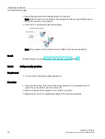
Page 46: ...ions that the Web server supports Home page Web page header area Siemens logo Changing security questions Page 59 User name Logging out Page 60 Changing the password Page 59 Main navigation bar Menu icon Data Acquisition icon Page 50 Home page icon Page 44 Device Configuration icon Page 55 Setup Wizard icon Page 46 Port information display area Viewing the port information Page 45 Status indicator...

Page 47: ... one of the icons in the main navigation bar expands collapses its menu and sub menus if any 5 2 3 2 Viewing the port information See below for structure of the information display area of a port on the home page Status indicator light USS address 0 to 31 Port number Transmission baud rate Activation status port mode Inactive parameter ID Converter type ...

Page 48: ...of the port from the page for configuring the port Page 50 5 2 4 Quick configuration The Web server provides you with a setup wizard for quick converter configuration including port configuration and MindSphere configuration Requirement You can access the quick configuration page when any one of the following conditions is met You have finished setting security questions in the case of the first l...

Page 49: ...onverter by itself For more information see Section Identifying the converter optional Page 36 3 Assuming that you select the manual port mode click Converter Settings to start setting the basic parameters of the port Note When the automatic port mode is selected the Converter Settings button is disabled In this case click Parameters to directly start configuring converter parameters skip to step ...

Page 50: ...t Page 76 You can also click Default to restore all the parameters to their default settings 10 The Web browser jumps back to the quick configuration home page Repeat steps 1 to 9 to complete configuring the remaining ports as desired 11 Click Next in the lower right corner to start configuring MindSphere 12 In the window that opens choose whether to use a proxy server for transferring data to Min...

Page 51: ...le txt Note The txt file is produced from the onboarding key value that is downloaded from MindSphere For more information see Section Transferring configuration to the device Page 70 16 Click Onboard to upload the file onto the SINAMICS CONNECT Then a pop up box displays asking whether to continue the operation 17 Click OK a message box displays indicating that the file uploading succeeds Note Cl...

Page 52: ...vice and jumps back to the home page Note After you click button b or c a pop up box displays asking whether to continue the operation 19 After checking the port configuration results that display click button c to submit the settings Result The Web browser jumps back to the home page 5 2 5 Acquiring the converter data To acquire data from the converter and then synchronize the data to MindSphere ...

Page 53: ...automatic port mode you need to press the USER button on the device to complete the identification or wait for the device to identify the converter by itself For more information see Section Identifying the converter optional Page 36 4 Assuming that you select the manual port mode click Converter Settings to start setting the basic parameters of the port Note When the automatic port mode is select...

Page 54: ...cancel the settings Note Clicking Default resets all the parameters to their default settings in the predefined parameter list Page 76 11 The Web browser jumps back to the port configuration home page Repeat steps 2 to 10 to configure other ports as desired 12 The Web browser jumps back to the port configuration home page Click View Modifications in the lower right corner to view the port configur...

Page 55: ...oduced the configuration file txt from the onboarding key value that is downloaded from MindSphere Procedure 1 Choose the MindSphere Configuration menu from the navigation bar 2 On the MindSphere configuration home page choose whether to use a proxy server for transferring data to MindSphere via the check box Note By default the check box is deselected 3 Assuming that you choose to use a proxy ser...

Page 56: ...ced from the onboarding key value that is downloaded from MindSphere For more information see Section Transferring configuration to the device Page 70 6 Click Onboard to upload the file onto the SINAMICS CONNECT Then a pop up box displays asking whether to continue the operation 7 Click OK a message box displays indicating that the file uploading succeeds Note Clicking Delete removes the uploaded ...

Page 57: ...ccessed the home page after a successful normal login Procedure 1 Choose the Reboot SINAMICS CONNECT menu from the navigation bar A pop up box displays asking whether to continue the operation 2 Click OK a pop up box displays indicating that the rebooting is ongoing with the remaining time being displayed When the time expires the rebooting is completed Result The device is rebooted successfully N...

Page 58: ...saving succeeds and the device will be upgraded after a restart Note Clicking Delete removes the uploaded file 5 Restart the device and the upgrade is executed automatically Note After the upgrade completes the Web browser displays the current version number of firmware in the upper left corner of the Web pages Result If the upgrade succeeds the updated version of firmware runs directly after rest...

Page 59: ...e log file txt to the local drive on your PC Result The Web browser stays on the current page 5 2 6 4 Synchronizing time The Web server provides you with the function of synchronizing the time of the SINAMICS CONNECT when the system time is lost Requirement You have accessed the home page after a successful normal login Procedure 1 Choose the Synchronize Time menu from the navigation bar 2 On the ...

Page 60: ...Note Make sure that you set the local time accurately permissible time error 2 minutes Improper settings with a time error of greater than 2 minutes may cause a failure of data transfer 3 Click Save to activate the time settings Then a pop up box displays asking whether to continue the operation 4 Click OK and then a pop up box displays indicating that the rebooting is ongoing with the remaining t...

Page 61: ...ogged in successfully Requirement You have accessed the home page after a successful normal login Procedure 1 Hover on the user name in the upper right corner of the Web page 2 Select Change Password from the drop down list 3 Change the password by following the steps described in Section Changing the default password Page 39 Result The Web browser brings you to the normal login page Page 41 5 2 7...

Page 62: ...ng security questions Page 40 Result The Web browser brings you to the normal login page Page 41 5 2 7 3 Logging out The Web server provides you with the logout function from any page that displays after a successful login Requirement You have accessed any one Web page that displays after a successful login Procedure 1 Hover on the user name in the upper right corner of the Web page 2 Select Logou...

Page 63: ...anager Page 62 In this step you create an asset in MindSphere Transferring configuration to the device Page 70 In this step you establish the connection between SINAMICS CONNECT and MindSphere Data mapping Page 73 In this step you map the data of the SINAMICS CONNECT to the aspects and variables of the asset in MindSphere 6 2 Logging in to MindSphere Requirement You have an account for MindSphere ...

Page 64: ...s types and aspects In order to create an asset in Asset Manager you need to perform the following steps 1 Creating aspects and variables Page 62 In this step you create aspects and variables you want to use in MindSphere 2 Creating a type Page 66 In this step you create a type with the previous created aspects and variables 3 Creating an asset Page 69 In this step you create a new asset by select...

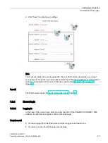
Page 65: ...gged in to MindSphere You have accessed the Aspects page in Asset Manager Procedure 1 To create a new aspect click and the Create aspect window is open Note Make sure your user role is TenantAdmin otherwise you cannot create aspect type or asset in Asset Manager 2 Under Aspect information enter the name of the aspect in the Name input filed for example SC_port1 Note You are recommended to name the...

Page 66: ...Dynamic 5 Under Variables click the button Add variable 6 Proceed with the following steps for each variable for example port1_Act_filtered_DC_link_volt 6a Enter the name of the variable 6b Select the data type of the variable 6c Enter the unit of the variable 7 Click Add variable to add the next variable Repeat step 6 until all of your variables are added ...

Page 67: ... defined parameter list For more information see Section Parameter list Page 76 8 Confirm the entries with Save and the new aspect with its variables is now created Note Once you have created the aspect you cannot edit the Type ID Name and the Description of the aspect Once you have saved the variables you cannot remove or edit the variables 9 Repeat steps 1 to 8 until all of your eight aspects ar...

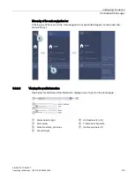
Page 68: ... the type on which they are based Within the type you can define which aspects are integrated into the template Types user interface Navigation bar Create a new type Parent type Hierarchy Search field Detail view of type Selection list Operating tools Requirement You have created an aspect You have accessed the Types page in Asset Manager Procedure 1 Select BasicAgent from the selection list and c...

Page 69: ...te Make sure that you create the type under the parent type MindConnect Lib 4 The Create type window is open Under Type information enter a name for the type for example SINAMICS CONNECT 5 When required enter the description of the type 6 Under Aspects select an aspect from the drop down list for example SC_port1 Note The Name input filed is automatically generated ...

Page 70: ...408 7 Click Add aspect 8 Repeat steps 6 to 7 until all your eight aspects are added to the type 9 To save the type click Save Note Once you have created the type you cannot edit the Parent Type Type ID Name and the Description of the type Result You created a new type The new type with eight aspects is now available in the presets ...

Page 71: ...igation bar Create a new asset Parent asset Hierachy Search field Detail view of asset Selection list Operating tools Requirement You have created a type with eight aspects and their variables You have accessed the Assets page in Asset Manager Procedure 1 To create a new asset click and the Select type window is open 2 Select the type for your new asset for example SINAMICS CONNECT ...

Page 72: ...ies with Save Result The new asset is now available in the selection list 6 4 Transferring configuration to the device Requirement The device is connected to the Internet and powered on For more information see Section Connecting the device to MindSphere network Page 32 The device is connected to a PC For more information see Section Connecting the device to a PC Page 32 You have access to the SIN...

Page 73: ...Click the asset you have created for example SINAMICS CONNECT_1 2 Click the MindConnect Lib box 3 The Configure MindConnect Lib page is open Select the security profile SHARED_SECRET from the drop down list 4 Click Save Note Only the security profile SHARED_SECRET is applicable to the SINAMICS CONNECT 5 The Edit boarding configuration page is open Click Generate onboarding key ...

Page 74: ...cated in the configuration object 7 Save the configuration object into a TXT file and name it in the format of XXX txt for example onboardfile txt Make sure that you do not modify the configuration object 8 Now the configuration is exported Import the configuration to the device 1 Import the configuration to the device via the Web server For more information about how to operate on the Web server ...

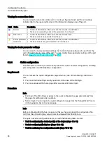
Page 75: ...boarding The connection between the device and MindSphere is to be established Solid grey Not onboarded The device is disconnected from MindSphere Online status Color Online status Description Solid green Online The device is transmitting data to MindSphere Solid grey Offline The device is not transmitting data to MindSphere 6 5 Data mapping Data mapping means matching variables of an aspect with ...

Page 76: ... graphic below shows the default data source and data points loaded after the device is onboard Note Do not click Enter the edit mode to edit the default data source or data points by yourself otherwise it will cause data mapping failure 3 Click the Data mappings tab 4 Select the data point you want to map from the list for example port1_Act_filtered_DC_link_volt and click Link variable 5 Select t...

Page 77: ...data mapping added Note Only units and data types that match exactly with the aspects and variables are available If the units or the data types are not matched the variable cannot be connected to the data point also case sensitive 9 Repeat steps 4 to 8 until all of your data points are mapped Note You cannot map the data point named Others It is an automatically generated data point for time seri...

Page 78: ...rotor_s peed Displays calculated rotor speed based on r0021 rpm Double 5 s Active 5 r0031 r0031 r0031 portX_Act_filtered_torque Displays electrical torque NM Double 5 s Active 6 r0039 0 3 r0039 0 r0039 0 portX_Energy_consumpt_ meter Displays electrical en ergy used by converter since display was last reset kWh Double 5 s Active 7 r0207 0 r0207 0 r0207 0 portX_Rated_converter_cu rrent Displays rate...

Page 79: ... 5 portX_Fault_code_6 Recent fault trip 6 Double 5 s Active 20 r0947 6 r0947 6 r0945 6 portX_Fault_code_7 Recent fault trip 7 Double 5 s Active 21 r0947 7 r0947 7 r0945 7 portX_Fault_code_8 Recent fault trip 8 Double 5 s Active 1 The data type in this column is the data type used in MindSphere 2 In this column X port No ranges from 1 to 8 For example for port 1 the name of parameter r0026 is port1...

Page 80: ...s Explosion of the batteries and the released pollutants can cause severe physical injury Worn batteries jeopardize the function of the device Replace the battery every 5 years Replace the lithium battery only with the type recommended by the manufacturer Do not throw lithium batteries into fire do not solder on the cell body do not recharge do not open do not short circuit do not reverse polarity...

Page 81: ...e a UL BBCV2 certified lithium battery which meets the following requirements Technical data of the recommended battery Battery type BR2450A from Panasonic Nominal capacity 550 mAh Nominal voltage 3 V Maximum abnormal charging current 5 mA Requirement The device is disconnected from the power supply A replacement battery is available Procedure NOTICE Equipment damage due to times loss The time wil...

Page 82: ...mplemented by appropriately trained Siemens service personnel Please contact the Siemens service personnel for replacing the SD card 7 5 Recycling and disposal For environmentally friendly recycling and disposal of your old device please contact a company certified for the disposal of waste electrical and electronic equipment and dispose of the old device as prescribed in the respective country of...

Page 83: ...er the modifications are made The device meets the guidelines listed in the following sections EU Declaration of Conformity The associated declaration of conformity is available on the Internet at the following address EU Declaration of Conformity https support industry siemens com cs ww en ps 25435 cert UL approval The following approvals are available for the device Underwriters Laboratories UL ...

Page 84: ...onic components or modules are labeled as electrostatic sensitive devices The following abbreviations are commonly used for electrostatic sensitive devices ESD Electrostatic sensitive device ESD Electrostatic Sensitive Device as a common international designation Electrostatic sensitive devices can be labeled with an appropriate symbol NOTICE Damage to ESD due to direct touch Electrostatic sensiti...

Page 85: ...aximum electrostatic voltages with which a person is charged depending on humidity and material These values conform to the specifications of IEC 61000 4 2 Synthetic materials Wool Antistatic materials such as wood or concrete NOTICE Damage to ESD due to failure of grounding There is no equipotential bonding without grounding An electrostatic charge is not discharged and may damage the ESD Protect...

Page 86: ...properly grounded This way you avoid static discharge Avoid direct contact As a general rule do not touch electrostatic sensitive devices except in the case of unavoidable maintenance work Hold the modules at their edge so that you do not touch the connector pins or conductor paths This way the discharge energy does not reach and damage the sensitive components Discharge your body electrostaticall...

Page 87: ...ement NEC Class 2 or LPS according to the IEC EN DINEN UL 60950 1 2 In the event of low supply voltage the buffer time is reduced Electromagnetic compatibility Immunity with regard to conducted interference on the supply lines 2 kV according to IEC 61000 4 4 burst 1 kV according to IEC 61000 4 5 asymmetrical surge Noise immunity on signal lines 1 kV according to IEC 61000 4 4 burst length 30 m 2 k...

Page 88: ... ambient conditions The temperature values have been checked in accordance with IEC 60068 2 1 IEC 60068 2 2 and IEC 60068 2 14 For more information about permitted mounting positions see Section Permitted mounting orientation and mounting types Page 24 Ambient temperature Operation 0 C to 50 C 1 Storage transport 20 C to 70 C Gradient Operation 10 C h Storage 20 C h no condensation Relative humidi...

Page 89: ...liary components The information below applies to the horizontal mounting position of the device at an ambient temperature of 50 C and to the vertical mounting position of the device at an ambient temperature of 45 C Maximum total power of all components 6 W NOTICE Equipment damage due to overheat The power supply cannot make unlimited power available The auxiliary components consume energy and pr...

Page 90: ...rface overview Component interface Description Meaning PWR Power supply LED Power green SD SD card LED Micro SD card active green USB USB LED USB power 5 V available green OC Over current LED Over current red USER User LED Reserved RESET RESET button For a reset of the CPU USER USER button For converter identification X1 Ethernet port 1 RJ45 Ethernet connection 1 for the access to the Internet to ...

Page 91: ...description Meaning 1 BI_DA Bidirectional data A input output 2 BI_DA Bidirectional data A input output 3 BI_DB Bidirectional data B input output 4 BI_DC Bidirectional data C input output 5 BI_DC Bidirectional data C input output 6 BI_DB Bidirectional data B input output 7 BI_DD Bidirectional data D input output 8 BI_DD Bidirectional data D input output X1 P1 LAN LED Short description Meaning 1 LE...

Page 92: ...n 1 PE 17 PE Protective earth 4 2 PE4 8 16 PE8 Protective earth 3 M 15 M Signal ground 4 RX4 14 RX8 Receive data I for full duplex mode 5 TX4 13 TX8 Transmit data O for full duplex mode 3 6 PE3 7 12 PE7 Protective earth 7 M 11 M Signal ground 8 RX3 10 RX7 Receive data I for full duplex mode 9 TX3 9 TX7 Transmit data O for full duplex mode 2 10 PE2 6 8 PE6 Protective earth 11 M 7 M Signal ground 12...

Page 93: ...minals for cable without ferrule Solid conductor cross section 0 2 mm2 to 1 mm2 Stranded conductor cross section 0 5 mm2 to 1 mm2 1 Remove the specified length see illustration of the outer sheath of the cable and make a PE conductor from the braided shield 2 Strip the specified length see illustration of the insulation at the end of the wire ...

Page 94: ... 5 mm2 Stranded conductor with non insulated ferrule cross section 0 25 mm2 to 0 5 mm2 1 Remove the specified length see illustration of the outer sheath of the cable and make a PE conductor from the braided shield 2 Strip the specified length see illustration of the insulation at the end of the wire 3 Insert the stripped end into the pin type terminal 4 Crimp the terminal using a crimping tool an...

Page 95: ... request form http www siemens com automation support request SINAMICS Digitalization www siemens com sinamics digitalization Your local representative http www automation siemens com mcms aspa db en Pages default aspx Training center http sitrain automation siemens com sitrainworld AppLang en Industry Mall https mall industry siemens com When contacting your local representative or Technical Supp...

Page 96: ...ing is based on so called virtual assets This can be anything such as a pump motor PLC an entire tool machine a production line a robot a crane a car a wind turbine and so on The data of an asset is collected and sent to MindSphere to make that data available for further processing and analytics Asset Manager Asset Manager is a Web Graphical User Interface for asset configuration According to thes...

Page 97: ... cloud services and applications whereas the SINAMICS CONNECT provides secure and easy connectivity from your converter to MindSphere In MindSphere the data acquired and submitted by the SINAMICS CONNECT is processed and stored for analysis and further management purposes For more information refer to the MindSphere documentation MindSphere Launchpad MindSphere Launchpad is the entry point for Com...

Page 98: ... 81 F Flash 86 G General technical specifications 85 I Identification data 20 Installation on a DIN rail 24 Installing Backup battery 79 Interfaces 86 M Marking EU Declaration of Conformity 81 MindSphere 61 Mounting Wall 27 Mounting position 24 Mounting type 24 N Noise emission 85 P Packaging 23 Checking 23 Removing 23 Power supply DC power supply 87 Processor 86 PROFINET 88 Protective measure Sta...

Page 99: ...Index SINAMICS CONNECT Operating Instructions 10 2018 A5E45421408 97 W Wall mounting 24 27 Weight 85 ...

Page 100: ......

Page 101: ......

Reviews: