49
FLUDEX 4612 en
Operating instructions 10/2017
The space between the shafts now suffices for the fitted hubs, if necessary, to be pulled off by means of
commercially available tools after releasing the axial fixture.
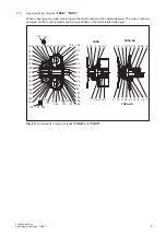
Located at the endface side in the hub in the hubcarrier part (120) are two tapped holes offset by 180°,
which may be used to insert drawing bolts (see figure 16).
1
2
3
4
5
6
Fig. 16:
Removing the FLUDEX coupling c
1
Shaft
2
Hub-carrier part
3
Drawing bolts
4
Pressure spindle
5
Bridge
6
Brake drum
Summary of Contents for FLENDER FLUDEX FNA
Page 2: ......


