007016_i_en_--
Building Technologies
2012-09-07
Control Products and Systems
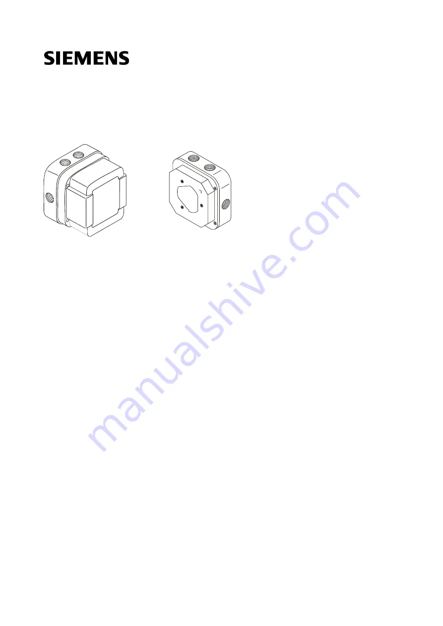
FDL241-9 Linear smoke detector
Technical Manual
Page 1: ...007016_i_en_ Building Technologies 2012 09 07 Control Products and Systems FDL241 9 Linear smoke detector Technical Manual ...
Page 2: ...on of its contents and communication thereof to others without express authorization are prohibited Offenders will be held liable for payment of damages All rights created by patent grant or registration of a utility model or design patent are reserved Issued by Siemens Switzerland Ltd Infrastructure Cities Sector Building Technologies Division International Headquarters Gubelstrasse 22 CH 6301 Zu...
Page 3: ...3 3 6 Signal processing 27 3 4 Accessories 30 3 4 1 Base for linear smoke detector FDLB291 30 3 4 2 Reflector for long distance prism DLR1191 30 3 4 3 Reflector for middle distance foil DLR1192 31 3 4 4 Reflector for short distance foil DLR1193 31 3 4 5 Short distance filter DLF1191 AA 31 3 4 6 Short distance filter DLF1191 AB 32 3 4 7 Extraneous light filter DLF1191 AC 32 3 4 8 Detector heating u...
Page 4: ... line 56 5 3 1 1 Use of unshielded cables 56 5 3 1 2 Use of shielded cables 57 5 3 2 Connection to a collective detector line 58 5 3 2 1 Use of unshielded cables 59 5 3 2 2 Use of shielded cables 60 5 4 Installing the reflector for long distance prism 61 5 5 Installing the reflectors for middle distance and short distance foil 62 6 Commissioning 63 6 1 Set parameter set 64 6 2 Installing the detec...
Page 5: ...5 Building Technologies 007016_i_en_ Fire Safety 2012 09 07 ...
Page 6: ...se This document contains all the information you will need on the linear smoke detector FDL241 9 Following the instructions consistently will ensure that the product can be used safely and without any problems In accordance with EN 62471 Photobiological Safety of Lamps and Lamp Systems the linear smoke detector falls into the Exempt Group ...
Page 7: ...r customer requirements Checks operability and approves the product for commissioning at the place of installation Is responsible for troubleshooting Has obtained suitable specialist training for the function and for the products Has attended the training courses for Product Engineer Installation personnel Assembles and installs the product components at the place of installation Carries out a per...
Page 8: ...ent identification The document ID is structured as follows ID code Examples ID_ModificationIndex_Language_COUNTRY multilingual or international A6V10215123_a_de_DE A6V10215123_a_en_ A6V10315123_a_ _ Conventions for text marking Markups Special markups are shown in this document as follows Requirement for a behavior instruction Intermediate result of a behavior instruction End result of a behavior...
Page 9: ...DUD292 008331 List of compatibility for Sinteso product line 009718 Operation Intelligent detector tester FDUD293 A6V10229261 List of compatibility for Cerberus PRO product line A6V10332811 Mounting Commissioning Linear smoke detector FDL241 9 1 2 Technical terms Term Explanation ABS Acrylonitrile butadiene styrene plastic ASA Advanced Signal Analysis DLR Reflector FDL Linear smoke detector FDnet ...
Page 10: ...pecifications format yyyy mm dd reference to standard EN 62471 added editorial changes h 05 2011 Content and layout revised history of changes redefined and standardized Reference documents adapted g 01 2009 New label for measurements f 10 2007 Supplements in the technical data line separator standard EN 54 17 LPCB approvals information about air humidity e 08 2006 Shielding added in connection di...
Page 11: ...2 09 07 The table below shows the published language versions and country variants with the corresponding modification index Modification index en_ de_ fr_ it_ es_ i X X X X X h X X X X X g X f X X e X X d X X c X X b X X X X X a X X X X X X published no publication with this modification index ...
Page 12: ...angers the type of danger or possible consequences measures and prohibitions examples of which are shown in the following table General danger Explosive atmosphere Voltage electric shock Laser light Battery Heat Signal word The signal word classifies the danger as defined in the following table Signal word Danger level DANGER DANGER identifies a dangerous situation which will result directly in de...
Page 13: ...s shown as follows WARNING Nature and origin of the danger Consequences if the danger occurs Measures prohibitions for danger avoidance How possible damage to property is presented Information about possible damage to property is shown as follows NOTICE Nature and origin of the danger Consequences if the danger occurs Measures prohibitions for danger avoidance ...
Page 14: ...dance with the electrotechnical regulations Wherever possible disconnect products from the power supply when carrying out commissioning maintenance or repair work on them Lock volt free areas to prevent them being switched back on again by mistake Label the connection terminals with external external voltage using a DANGER External voltage sign Route mains connections to products separately and fu...
Page 15: ...lts malfunctioning and safety risks Written confirmation must be obtained from Siemens and the corresponding safety bodies for modifications or additions Modules and spare parts Components and spare parts must comply with the technical specifications defined by Siemens Only use products specified or recommended by Siemens Only use fuses with the specified fuse characteristics Wrong battery types a...
Page 16: ...ury and damage to property in the event of a fire Read the Release Notes before you plan and or configure a fire detection installation Read the Release Notes before you carry out a firmware update to a fire detection installation NOTICE Incorrect planning and or configuration Important standards and specifications are not satisfied Fire detection installation is not accepted for commissioning Add...
Page 17: ...vity levels In accordance with EN 62471 Photobiological Safety of Lamps and Lamp Systems the linear smoke detector falls into the Exempt Group 3 1 1 Details for ordering Type Order no Designation FDL241 9 A5Q00002298 Linear smoke detector 3 1 2 Product version ES The product version ES provides the technical status of a device in terms of software and hardware The product version is provided as a ...
Page 18: ... product version Depending on the product and various approvals the product labels may differ in terms of the information type and layout Look for your device s order number on the product label You will find the product version after the order number 3 2 Setup The linear smoke detector consists of the detector base 1 the terminal block 2 the detector unit 3 and the hood 4 1 2 3 4 Setting up the l...
Page 19: ...ector unit 1 Holder for special filter 8 Safety screws 2 Holder for mirror with visor 9 DIP switch 3 Holder for notch 10 Connection for detector heating unit 4 Horizontal scale 11 Alarm indicator 5 Receiver lens 12 Connection for adjustment device 6 Knurled screw for horizontal setting 13 Vertical scale 7 Transmitter lens 14 Knurled screw for vertical setting ...
Page 20: ... reflector value values date action signal value notes Label for entering the measurements 3 3 Function The linear smoke detector smoke detector consists of a transmitter and a receiver and works according to the principle of light attenuation by smoke The transmitter transmits to the reflector a highly focused pulse shaped infrared ray If no smoke is present a large part of the infrared ray reach...
Page 21: ...d ray initially transmitted reaches the receiver and the electrical signal becomes weaker 1 2 3 4 2 5 Function of the linear smoke detector with smoke 1 Absorption 4 Smoke particle 2 Scattering 5 Infrared ray 3 Attenuated infrared ray The linear smoke detector measures the distance which enables an exact alignment of the smoke detector to the reflector when the detector is commissioned Due to dist...
Page 22: ...nection between the transmitter reflector and receiver Core range 2 In the core enough radiation energy is present to operate the system Scattering range 3 The radiation energy in the scattering range is insufficient and does not ensure the functionality of the system FDL DLR 1 2 3 Setup of the infrared ray 1 Effective range 3 Scattering range 2 Core range 1 2 3 DLR d 0 57 0 57 FDL Diameter of the...
Page 23: ...either direction and vertically by a maximum of 5 in either direction This adjustment range can be used for an optimum positioning of the devices In the case of detection distances greater than 50 m position the detector and reflector as close to opposite one another as possible This makes adjustment easier One turn of the knurled screw moves the infrared ray by approx 0 8 m per 100 m distance FDL...
Page 24: ...rections max 20 max 20 1 1 1 Reflectors with various inclinations 1 Reflector Reflector for long distance prism DLR1191 The reflector for long distance consists of a prism and a housing The retro reflecting prism has the shape of an even pyramid the lateral surfaces of which are made up from isosceles right angled triangles Light rays coming in through the base surface are completely reflected thr...
Page 25: ...witches which isolate the defective part in case of a short circuit on the detector line The rest of the detector line remains serviceable On a loop line all FDnet C NET devices remain fully functional after a simple error 3 3 4 Danger levels The detector can transmit the following danger levels to the control panel Danger level Meaning Comment 0 No danger Normal condition 11 Check situation You m...
Page 26: ...r exchanger and tester Meaning Measures no deviation Normal no fault is present The detector is fully functional None maybe excha 1 Observe information Compensation value is too high or too low Detector is fully functional reflection or dirt cannot however be compensated for In the case of dirt clean the detector and reflector and re initialize them In the case of reflection remove or cover reflec...
Page 27: ... for reaching a danger level is not only given by measurements below a certain response threshold moreover the smoke density progression is observed over a longer period of time and evaluated with ASAtechnology ASA Advanced Signal Analysis The detector processes the signal according to internal diagnoses and reports the result to the control panel Correction value The compensation value is the ref...
Page 28: ... on the sensitivity level of the parameter set selected the response threshold may be higher or lower Very sensitive Response threshold is 30 below the compensation value Sensitive Response threshold is 50 below the compensation value Standard Response threshold is 65 below the compensation value Response threshold for various sensitivity settings 1 Signal typical signal course during smoke genera...
Page 29: ...faults are thereby leveled out Further signal processing is based on the leveled signal Leveling characteristics 1 Unleveled signal 2 Leveled signal Time until alarm activation The table below shows the time until alarm activation for various internal detector diagnoses Internal detector diagnosis Time until alarm activation typical value Normal or slow fire 6 s Background noise or repeated open l...
Page 30: ...e with Linear smoke detector FDL241 9 Order no A5Q00003941 See also Installing the detector base 54 3 4 2 Reflector for long distance prism DLR1191 For reflecting the infrared ray of the linear smoke detector Prism shaped Reflection distance 20 100 m With a built in heating unit Compatible with Linear smoke detector FDL241 9 Order no BPZ 4787710001 See also Installing the reflector for long distan...
Page 31: ...he reflectors for middle distance and short distance foil 62 3 4 4 Reflector for short distance foil DLR1193 For reflecting the infrared ray of the linear smoke detector Micro prismatic foil Reflection distance 10 30 m Dimensions 100 x 100 x 2 5 mm Hole diameter 4 mm Compatible with Linear smoke detector FDL241 9 Order no BPZ 4787840001 See also Installing the reflectors for middle distance and sh...
Page 32: ...33160001 3 4 7 Extraneous light filter DLF1191 AC For filtering extraneous light during a high level of extraneous light Compatible with Linear smoke detector FDL241 9 Order no BPZ 5221480001 3 4 8 Detector heating unit DLH1191A For applications where there is danger of moisture condensation or icing Incl terminal block for the connection Compatible with Linear smoke detector FDL241 9 Order no BPZ...
Page 33: ...mance check on the linear smoke detector Compatible with Linear smoke detector FDL241 9 Order no BPZ 3685190001 3 4 11 Alarm test filter TF04 Alarm test filter for detector tester for linear smoke detector RE10 Absorption 77 Dimensions approx 170 x 85 mm Compatible with Linear smoke detector FDL241 9 Detector tester for linear smoke detector RE10 Adjustment kit FDLU291 Order no BPZ 4931090001 3 4 ...
Page 34: ... linear smoke detector 4 2 General planning information Between the detector and the reflector therer must be permanent undisturbed visual contact The infrared ray must not be interrupted by moving objects e g cranes ladders transportable objects cobwebs Vision impaired by dust vapor or smoke generated as a result of operation may impair the system The detector s installation location must be abso...
Page 35: ... and without hindrance Connect the adjustment device Set the detector optics Mount hood After commissioning for the first time the service personnel must be able to access the detector safely and with ease e g for maintenance and adjustment work See also Testing detectors 77 4 3 Planning in rooms with flat ceilings Please note the following points if you are installing detectors in rooms with flat...
Page 36: ...rface given the architectural circumstances The installation surface must be stable and vibration free See 45 If the room has one or more of the following circumstances you must also observe further information Narrow spatial circumstances Maintain the minimum distance 7 between two detectors See 47 Girders The detector can be installed in the ceiling panel between the girders or below the girders...
Page 37: ...tor or reflector 5 Detection distance 2 Minimum distance between two detectors 6 Width of monitoring area 3 Distance between detector and ceiling 7 Installation height 4 Room height 8 Minimum distances to ceilings walls etc Detection distance 5 Define the distance to be monitored Depending on this define the type and number of reflectors See 40 Room height 4 and installation height 7 Define the in...
Page 38: ...es Maintain the minimum distance 2 between two detectors See 47 Girders The detector can be installed in the ceiling panel between the girders or below the girders See 47 Glass panes Detection through glass panes and installation on glass panes are only possible under restricted circumstances See 49 Danger of moisture condensation Use the detector heating unit if there is a danger of moisture cond...
Page 39: ...detector must be slid sideways to the flatter roof incline Define the distance between the detector and the ceiling 2 using the room height 1 1 2 Position on ceilings with uneven inclination 1 Room height 2 Distance between detector and ceiling Example In the case of a room height of 10 m the distance between the detector and ceiling is 40 to 90 cm See also Distance between detector and ceiling 43...
Page 40: ... 1 reflector for middle distance foil DLR1192 50 65 m 4 reflectors for middle distance foil DLR1192 20 100 m 1 reflector for long distance prism DLR1191 Type and number of reflectors depending on the detection distance If you are using more than one reflector always position them close together and in a square shape The detection distance details are guidelines They depend on detector and reflecto...
Page 41: ...ce again measure the standardized signal value of the first detector If the standardized signal value has not changed since the first measurement the two detectors are not influencing one another If the standardized signal value has changed since the first measurement the two detectors are influencing one another Install a larger plate between the reflectors or take other suitable measures 4 Compl...
Page 42: ...rared ray must be used such that smoldering fires or smaller fires are detected 2 1 Detection of smoldering fires in high rooms on different levels 1 Detector 2 Reflectors The table below shows examples of the installation height for different room heights Room height m Topmost level m Middle level m Bottommost level m 6 approx 6 12 approx 12 6 7 20 approx 20 approx 12 6 7 See also Distance betwee...
Page 43: ...applies instead of the room height Maximum widths of monitoring area depending on the room height 4 8 Distance between detector and ceiling In order that the detector can detect smoke the infrared ray must be positioned immediately below the heat accumulation Detectors and reflectors must therefore be positioned at an ever greater distance from the ceiling as the room height increases The steeper ...
Page 44: ...Planning 4 Distance between detector and ceiling 44 Building Technologies 007016_i_en_ Fire Safety 2012 09 07 Inclined ceilings Inclined ceilings Distance between infrared ray and ceiling ...
Page 45: ...tructions These move due to the lengthwise expansion of steel Bricked walls on which a steel roof construction is placed In such cases the detector must be installed on a stable surface while the reflector can be installed on the unstable wall Example The example below illustrates how the infrared ray is deflected by the influence of heat on a hall roof s steel construction DLR FDL l β Δl h c Inco...
Page 46: ...n of the roof Δl Δl l ΔT α 80000 mm 40 K 38 4 mm 0 000012 K 1 Calculating the angle β β arctan h Δl arctan 4000 mm 38 4 mm 0 55 Calculating the deflection c β c tan l tan 0 55 80 m 0 77 m The deflection c is 0 77 m DLR FDL Possible solution Install the detector on the stable surface and install the reflector on the unstable wall ...
Page 47: ... infrared rays 4 11 Arrangement with girders The detector can be positioned in the ceiling panel between the girders or below the girders Girders include building elements e g air conditioning ducts installed at a distance of at maximum 15 cm below the ceiling Position in the ceiling panel between girders The detector must be positioned in the ceiling panel between the girders if the height of the...
Page 48: ...nts apply The height of the girders is less than 20 of the total room height The width of the ceiling panel is at most 50 of the maximum width of monitoring area The ceiling panel surface is a maximum of 200 m2 Only the room height h up to the girder is relevant when calculating the width of monitoring area 100 h 20 min 30cm Position below girders See also Width of monitoring area 43 ...
Page 49: ...enetrate one glass pane The detection distance is reduced by 20 m per glass pane Detection is faultless when the standardized signal value is less than 5 when the reflector is covered Glass panes may never be at a right angle to the infrared ray see example below Glass panes must never be installed at an angle to the infrared ray in which the glass pane acts as a mirror and can reflect the infrare...
Page 50: ... at an angle of 5 to 10 to avoid unwanted reflection 4 13 Measures against moisture condensation Moisture condensation on the detector or reflector can cause faults and false alarms Moisture condensation can occur e g when the detector or reflector is installed in a room with cool outer walls where high air humidity and rapid temperature increases can be expected as a result of sunshine on a non i...
Page 51: ...istance interruption distance measuring less than 40 of the initialization distance the Distance interruption fault occurs An alarm is suppressed When the signal drops below the alarm threshold during the fault an alarm is actuated after 40 s After canceling the fault any possible alarm is delayed for 40 s With distances of less than 7 m the distance is not evaluated With distances of less than 7 ...
Page 52: ...nnected and checked in line with the country specific installation guidelines Sequence 1 Switch detector over to collective operation optional 2 Installing the detector base 3 Electrical connection 4 Installing the reflector for long distance prism 5 Installing the reflectors for middle distance and short distance foil Information on the individual steps can be found in the following chapters The ...
Page 53: ...etector is switched over automatically switch it manually to collective operation before installing The detector always switches automatically from collective operation to FDnet C NET operation Procedure Note the positive and negative poles The detector base must not be connected to the detector line 1 Connect the detector base to a DC 12 V to 28 V source of DC voltage e g a battery according to t...
Page 54: ... you require for cable entry Note the arrows in the detector base indicating which side should be at the top 2 If necessary screw the M20 x 1 5 metal cable gland into the openings 3 Install the detector base on a stable vibration free surface with two screws 4 Guide the cables from the detector line and external alarm indicator into the detector base You will also need a 24 V supply if you are usi...
Page 55: ...damp and or corrosive environments Note the positive and negative poles Only connect one wire per terminal This is the only way of ensuring a problem free connection over the device s entire service life Wherever possible use twisted unshielded cables Shielded cables are only required in special cases such as strong high frequency fields This also applies to connecting the external alarm indicator...
Page 56: ...indicator according to the collective connection diagram may be migrated to the FDnet C NET without any changes Note document 001508 for installation calculation of the capacity layer 5 3 1 1 Use of unshielded cables The connection is established from base to base using twisted or non twisted wire pairs LINE 1 2 3 4 2 4 LINE _ _ _ LINE _ _ _ LINE _ _ _ LINE _ _ _ LINE _ _ _ Connection diagram for ...
Page 57: ...in the detector base with auxiliary terminals DBZ1190 xx There are two ways of connecting external alarm indicators LINE 1 2 3 2 4 A B 4 3 3 LINE _ _ _ LINE _ _ _ LINE _ _ _ LINE _ _ _ LINE _ _ _ Connection diagram for addressed detector line with and without external alarm indicators with shielded cables 1 Control panel 3 Auxiliary terminals DBZ1190 xx 2 Detector 4 External alarm indicator ...
Page 58: ... DBZ1190 xx Variant B 1 Connect the positive pole of the external alarm indicator to the positive pole for the external alarm indicator on the detector 2 Leave the negative pole for the external alarm indicator on the detector unoccupied 3 Connect each of the two negative poles of the external alarm indicator separately to both negative poles of the detector line The two negative connections of th...
Page 59: ...pending on control panel Standard circuitry With standard circuitry the external alarm indicator is connected to the positive and negative poles of each detector Wire saving cabling NOTICE Cabling for new sites Wire saving cabling in external alarm indicators is prohibited for new sites With wire saving cabling the external alarm indicator is connected as follows The external alarm indicator must ...
Page 60: ...rm indicator on the detector 2 Connect the negative pole of the external alarm indicator to the negative pole for the external alarm indicator on the detector 3 Connect the shielding of the connection cable between the external alarm indicator and detector on the detector side to the positive pole for the external alarm indicator via an auxiliary terminal DBZ1190 xx Variant B 1 Connect the positiv...
Page 61: ... according to the planning information 1 Install the base 1 with two screws on a level surface 2 Install the prism unit 2 on the base with four screws The reflector is installed Installation with heating unit Note the positive and negative poles Only connect one wire per terminal This is the only way of ensuring a problem free connection over the device s entire service life The installation locat...
Page 62: ...e base 5 Connect the wires to the terminals for the heating unit 3 according to the connection diagram 6 Install the prism unit 2 on the base with four screws See also Planning 34 5 5 Installing the reflectors for middle distance and short distance foil WARNING Danger of falling Bodily injury When installing use a secured ladder or work platform The installation location of the reflector is define...
Page 63: ...rameter set 2 Install detector unit 3 Install detector heating unit optional 4 Insert filter in detector optional 5 Commissioning the adjustment device 6 Checking the signal level and distance 7 Preliminary setting of the detector optics optional 8 Fine tuning of the detector optics 9 Initializing the detector 10 Testing detectors The types are described in the following chapters ...
Page 64: ...itches in the detector unit Use DIP switches 1 to set the parameter set you want see table below 1 Detector unit with DIP switches Parameter set DIP switch No Name Alarm for n attenuation 1 2 3 4 5 6 01 Standard with open line 65 ON OFF OFF OFF OFF OFF 02 Standard with British Standard Alarm 65 OFF ON OFF OFF OFF OFF 03 Sensitive with open line 50 ON ON OFF OFF OFF OFF 04 Sensitive with British St...
Page 65: ...en installing use a secured ladder or work platform The terminal block is installed in the detector base 1 Insert the detector unit 1 in the base with the terminal block 2 with the LED pointing downwards 2 Fasten the detector unit with four screws 3 Ensure that the screws are tightened 1 2 3 Installing the detector unit 1 Detector unit 3 Screws 2 Detector base with terminal block ...
Page 66: ...detector heating unit optional You must install the detector heating unit DLH1191A if there is a danger of moisture condensation To do this you need a 24 V supply 1 Insert the detector heating unit in the detector 2 Connect the detector heating unit to the printed circuit board Installation of the detector heating unit See also Accessories 30 ...
Page 67: ...n distances and strong extraneous light you may have to use a filter 1 Select the filter according to the planning information Short distance filter DLF1191 AA Short distance filter DLF1191 AB Extraneous light filter DLF1191 AC 2 Insert the filter 1 in the detector 1 Inserting the filter See also Accessories 30 Measures for short distances 41 Measures for strong extraneous light 51 ...
Page 68: ...suspension chain of the adjustment device 3 The adjustment device hangs on the detector You therefore have your hands free to undertake commissioning work Connecting the adjustment device The detector line is switched on 1 Connect the adjustment device 3 electrically to the detector To do so use the MC Link cable enclosed in the delivery and the connecting sockets 2 on the detector and on the adju...
Page 69: ...before initialization Must be between 255 and 1195 for initialization Otherwise initialization is not possible Top left 100 Standardized signal value as of the current compensation value During initialization the signal level is equalized to the compensation value 100 Bottom left 50m Distance in meters between detector and reflector Top right Adjust Detector not yet initialized Bottom right OK Las...
Page 70: ... with the knurled screws the vertical scale 7 with the knurled screw 8 the horizontal scale 1 with the knurled screw 2 3 Set the Adjust menu with the button 4 on the adjustment device 4 Read the indicators for the signal level and the distance from the adjustment device If the signal level is over 100 and the distance indication matches the detection distance continue fine tuning the detector opti...
Page 71: ...ctor is not mounted on an even surface 3 4 5 6 7 8 9 3 2 1 Checking the signal level and distance 1 Horizontal scale 6 Connection sockets 2 Knurled screw for horizontal adjustment 7 Vertical scale 3 Safety screws 8 Knurled screw for vertical adjustment 4 Button 9 Opening for cable entry 5 Adjustment device Example Signal level and distance indication in the Adjust menu 555 Adjust 50m See also Prel...
Page 72: ...ror 1 and the front sight 2 must be free from clearance 2 Ensure that the two safety screws 5 are loosened 3 Align the detector optics to the reflector using the knurled screws 3 knurled screw 6 for vertical setting knurled screw 4 for horizontal setting The reflector 3 and the front sight 2 must be on the axis of the circular mark on the mirror 4 Simultaneously check the signal level and the dist...
Page 73: ...ning for cable entry 5 Button When you change the setting the course of the signal is trapezoidal see figure below For optimum setting of the detector optics the setting must be in the middle of the trapezoid point D If the detector optics is not optimally set e g between points B and A problems and faults may occur during operation e g greater susceptibility to mechanical changes y x B C D A Sub ...
Page 74: ...e g the number of knurled screw turns or mark the scale 4 Turn the knurled screws forwards again until the standardized signal value is as high and constant as possible Continue turning until the standardized signal value decreases considerably point C 5 Note point C Count e g the number of knurled screw turns or mark the scale 6 Turn the knurled screws back until you reach the middle between poin...
Page 75: ... is switched on Setting of the detector optics is complete 1 Remove the sealing plug 1 from the hood 2 Connect the MC link cable to the connection socket 2 of the detector The standardized signal value and the detection distance are displayed in the Adjust menu on the adjustment device Example 1133 50m Adjust FDL241 9 commissioning adjustment data values displayed on adjustment device distance m d...
Page 76: ...tment data values displayed on adjustment device distance m deviate signal covered reflector value values date action signal value 100 50m OK The detector is initialized Troubleshooting during initialization If the standardized signal value is not within 100 3 or if the detection indication displayed deviates by more than 10 from the effective detection distance repeat the initialization process f...
Page 77: ...al value 2 50m OK 2 3 Stick a label on the hood at the top or side The other label is intended for system documentation Activating the test alarm 1 On the control panel switch off the remote transmission of alarms To do this set the Detector test operating mode on the control panel 2 Hold the alarm test filter TF04 in front of the hood such that it covers the detector optics The detector activates...
Page 78: ...he remote transmission of alarms To do this set the Detector test operating mode on the control panel 2 Hold the alarm test filter TF04 in front of the hood such that it covers the detector optics The detector activates an alarm after around 10 seconds 3 On the control panel switch the remote transmission of alarms back on 4 Check the detector for mechanical damage 5 Replace detectors that do not ...
Page 79: ...tment device must not deviate by more than 3 from the value entered under Deviate signal on the label Check the coverage area for short term changes e g dirt smoke vapor insecure installation or installation surface It is possible that the compensation value has not yet been updated Compare the values with those of the last commissioning session Enter the values on the label in the hood and in the...
Page 80: ...olvents or steam blasters Clean the protective hood and the reflector on a regular basis The interval depends on the ambient conditions e g degree of soiling Use either a dry soft cloth or a damp cloth together with window cleaner or a mild soap solution After cleaning check the detector s function according to the information provided in the chapter Performance check 78 In case of strong soiling ...
Page 81: ...ection distance influenced by dust vapor or mist Select a less sensitive parameter set The detector sporadically triggers false alarms The sun or other strong sources of light directly shine on the detector Avoid direct contact with sunlight or use an extraneous light filter DLF1191 AC The ray is reflected not only by the reflector but also by other objects e g ventilation ducts This results in to...
Page 82: ...ction factor 10 Alarm voltage at alarm current 1 15 mA DC 5 10 V 35 mA DC 18 22 V 50 mA DC 26 28 V Alarm current at operating voltage DC 5 28 V 4 50 mA Reset voltage DC 2 4 V Reset time at reset voltage DC 2 V 1 2 s Protocol Collective with and without current limitation Compatibility See List of compatibility Line separator Line voltage Nominal DC 32 V Vnom Minimum DC 12 V Vmin Maximum DC 33 V Vm...
Page 83: ...etector line Control panel specific Device characteristics Infrared transmitter Wavelength 950 nm Pulse frequency 4 Hz Compensation if the ray attenuates Compensation speed 2 3 h Alarm integration 6 16 s Detection distance Without filter 10 100 m With filter for short distance DLF1191 AA 8 12 m With filter for short distance DLF1191 AB 5 10 m Detector heating unit DLH1191A Operating voltage DC 20 ...
Page 84: ...gnetic compatibility 1 MHz 1 GHz 50 V m 1 GHz 2 GHz 30 V m Mechanical data Dimensions L x W x H 135 x 135 x 115 mm Material Detector base ABS PC Blend Hood ABS PC Blend Color RAL 9010 pure white Standards European standards EN 54 12 EN 54 17 EN 62471 International standards IEC 60529 ISO 9001 ISO 9004 Siemens standards SN 36350 Approvals EC Certificate of Conformity construction products FDL241 9 ...
Page 85: ...or linear smoke detector FDLB291 135 135 4 5 153 Base for linear smoke detector FDLB291 with linear smoke detector FDL241 9 45 M20 x 1 5 115 Reflector for long distance prism DLR1191 45 65 M20 x 1 5 Reflector for middle distance foil DLR1192 and reflector for short distance foil DLR1193 100 200 100 200 2 5 4 0 ...
Page 86: ...s have been undertaken Use of reusable materials Use of halogen free plastics Electronic parts and synthetic materials can be separated Larger plastic parts are labeled according to ISO 11469 and ISO 1043 The plastics can be separated and recycled on this basis Electronic parts and batteries must not be disposed of with domestic waste Take electronic parts and batteries to local collection points ...
Page 87: ...r optics Fine tuning 74 Preliminary setting 72 Detector unit 19 Diagnosis levels 26 Difference in temperature 45 Dimensions 85 Disposal 86 Distance Detector ceiling 43 Detector detector 47 Distance measuring 21 E Electrical connection 55 End of line 58 59 60 Environmental compatibility 86 ES Product version 17 External alarm indicator 55 56 57 Extraneous light 51 Extraneous light filter 51 67 F Fa...
Page 88: ...or middle distance foil 25 Reflector for short distance foil 25 Reflector for long distance prism 24 61 Reflector for middle distance foil 25 62 Reflector for short distance foil 25 62 Remedying faults 81 Repair 81 Response threshold 28 Room height 42 S Sensitivity 28 51 Short distance filter 67 Short circuit Line separator 25 Sighting system 72 Signal processing 27 Signal value Standardized 27 Sm...
Page 89: ...Index 89 Building Technologies 007016_i_en_ Fire Safety 2012 09 07 ...
Page 90: ...rnational Headquarters Gubelstrasse 22 CH 6301 Zug Tel 41 41 724 24 24 www siemens com buildingtechnologies 2004 2012 Copyright Siemens Switzerland Ltd Technical specifications and availability subject to change without notice Document ID 007016_i_en_ Manual FD20 FD720 Edition 2012 09 07 Register 3 ...