7SG11 Argus 8 Description of Operation
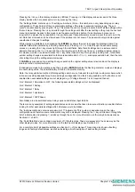
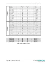
On two pole Argus 8 variants there are a total of 4 status inputs available in the relay. Of these three have a
common negative supply and one is electrically isolated from the rest.
Standard three pole Argus 8 relays have 1 status input. One type of expansion card includes an extra 4 status
inputs giving a total of 5. Another type of expansion card includes an extra 8 status inputs giving a total of 9.
Tables 1 and 2 show the number of status inputs available for each type of relay.
All status inputs are fully user programmable and each has a pick-up and drop-off timer. These timers allow
software filtering to be applied, which provides security in the presence of any induced A.C. voltages in the
external wiring. If high-speed operation is required then the pick-up delay should be set to zero.
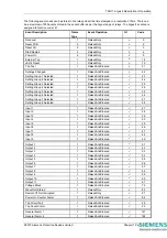
Each of the status inputs can be programmed to perform one of the following functions :
•
Inhibit operation of any one or more protection functions.
•
Select an alternative settings group.
•
Trigger storage of a waveform record.
•
Synchronise the real-time clock.
•
Reset latched output relays.
•
Energise an output relay.
•
Register a Trip by an external device.
•
Raise an alarm annunciation.
Additionally, each status input can have its operating logic inverted with the Status Invert feature.
For a list of terminal numbers and their usage see Tables 4 and 5 at the back of this section.
2.5 Self
Monitoring
The relay incorporates a number of self-monitoring features. Each of these features can initiate a controlled reset
sequence, which can be used to generate an alarm output. In addition, the Protection Healthy LED will give visual
indication.
A watchdog timer continuously monitors the microprocessor and the relay program memory is continuously
checked for data corruption using a cyclic redundancy check (CRC) routine. The internal voltage supply rails are
also continuously supervised and the microprocessor is reset if any of the rails are detected to be outside of their
working ranges. Any failure is detected in sufficient time so that the microprocessor can be shut down in a safe
and controlled manner.
2.6 Measuring
Principles
The input phase voltages to the relay are passed through voltage transformers, which step down the phase
voltages to levels which are suitable for the electronic input stage of the relay. The transformers also provide
essential isolation between the power system and the relay. The output of the transformers are differential signals
which are passed through lowpass filters and then from the voltage transformer board to the processor / analogue
board. Here the signals are fed to differential amplifiers which have excellent common-mode rejection. These will
reject any high frequency noise which may have coupled to the differential pair signals.
The single-ended output from the differential amplifiers is then fed to gain switching amplifiers which maximise the
signal gain to provide optimum measurement resolution. From here the signals are fed to the ADC where they are
sampled at a rate of 32 samples per power system cycle. (The dynamic range of the analogue-to-digital converter
(ADC) is increased with this gain switching method.)
The main signal processing algorithm in the relay is a discrete fourier transform (DFT) which is performed on each
phase input. The DFT extracts the power system fundamental frequency component from the input voltages,
effectively filtering out noise, D.C. and harmonics. The DFT is tuned for either 50 or 60Hz, depending upon the
system frequency setting. Output from the DFT calculations are real and imaginary components for each voltage
input.
The real and imaginary components are used to derive the magnitude quantity, which is then scaled to give a
RMS value. Part of the DFT calculation includes extra filtering which smoothes the real and imaginary
components, giving reduced ripple on the RMS calculation for off-system frequency conditions. In addition, a
lookup table is used to compensate for magnitude variations from the output of the RMS calculation for 47-62Hz
frequencies.
The real and imaginary components output from the DFT module are also used to derive the phase of the input
signal. The frequency is derived from the rate-of-change of the phase angle calculation. In addition, negative
phase sequence (NPS) and zero phase sequence (ZPS) quantities are also derived from the output of the DFT
calculation. The DFT ensures that D.C. and harmonics are rejected and so guarantees accurate and stable
©2010 Siemens Protection Devices Limited
Chapter 1 Page 7 of 20


