DESCRIPTION
1-5
Document No.: COM-00-05-16 June 2006, Revised June 2014
Version: C.1
Port No. Name
Description
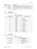
J3A/J3B
Second Ethernet
interface
Dual RJ45 connectors for inserting 12V DC at 1 Amp to power
Safetran Ethernet Radio A53325. The wiring for J3A is non-standard.
J4
Echelon and
power interface
6-Pin connector provides two pins for the twisted-pair Echelon
interface. It also includes 2 pins for 9 Volts to 24 Volts DC battery
power.
1.3.1.1
Pinouts for J1
The following table shows the pinouts for J1.
Table 1-2. Pinouts for J1
Pin Number
Name
I/O
Signal Description
6, 8, 10, 11, 20, 21, 22, 23, 25
Not Used
---
2
TXD1-
O
Tx Data
3
RXD1-
I
Rx Data
4
RTSO1-
O
Ready To Send
5
CTSI1-
I
Clear To Send
1, 7
Ground
I
9
RXC1+
I
Rx Clock
12
TXCI1+
I
Tx Clock
13
CTSI1+
I
Clear To Send
14
TXD1+
O
Tx Data
15
TXCI1-
I
Tx Clock
16
RXD1+
I
Rx Data
17
RXC1-
I
Rx Clock
18
TXCO1+
O
Tx Clock
19
RTSO1+
O
Ready To Send
24
TXCO1-
O
Tx Clock
1.3.1.2
Pinouts for J2
The following table shows the pinouts for J2.
Table 1-3.
Pinouts for J2
Pin No. Name
I/O
Signal Description
1
TX+
O
Transmit data +
2
TX-
O
Transmit data -
3
RX+
I
Ethernet Receive data +
6
RX-
I
Ethernet Receive data -
4, 5, 7, 8 N/C
Not used


