background image

35

8019897/V2-0/2017-12| SICK

O P E R A T I N G   I N S T R U C T I O N S   |  PowerCEMS100

Subject to change without notice

COMMISSIONING

6

6.9

Restarting after longer shutdown

Contact SICK Customer Service to clarify individual precautionary measures required for 
a restart after a longer shutdown (several weeks).

Ensure the following as preparatory work for clarification:
– Check the system and system components are ready for operation,

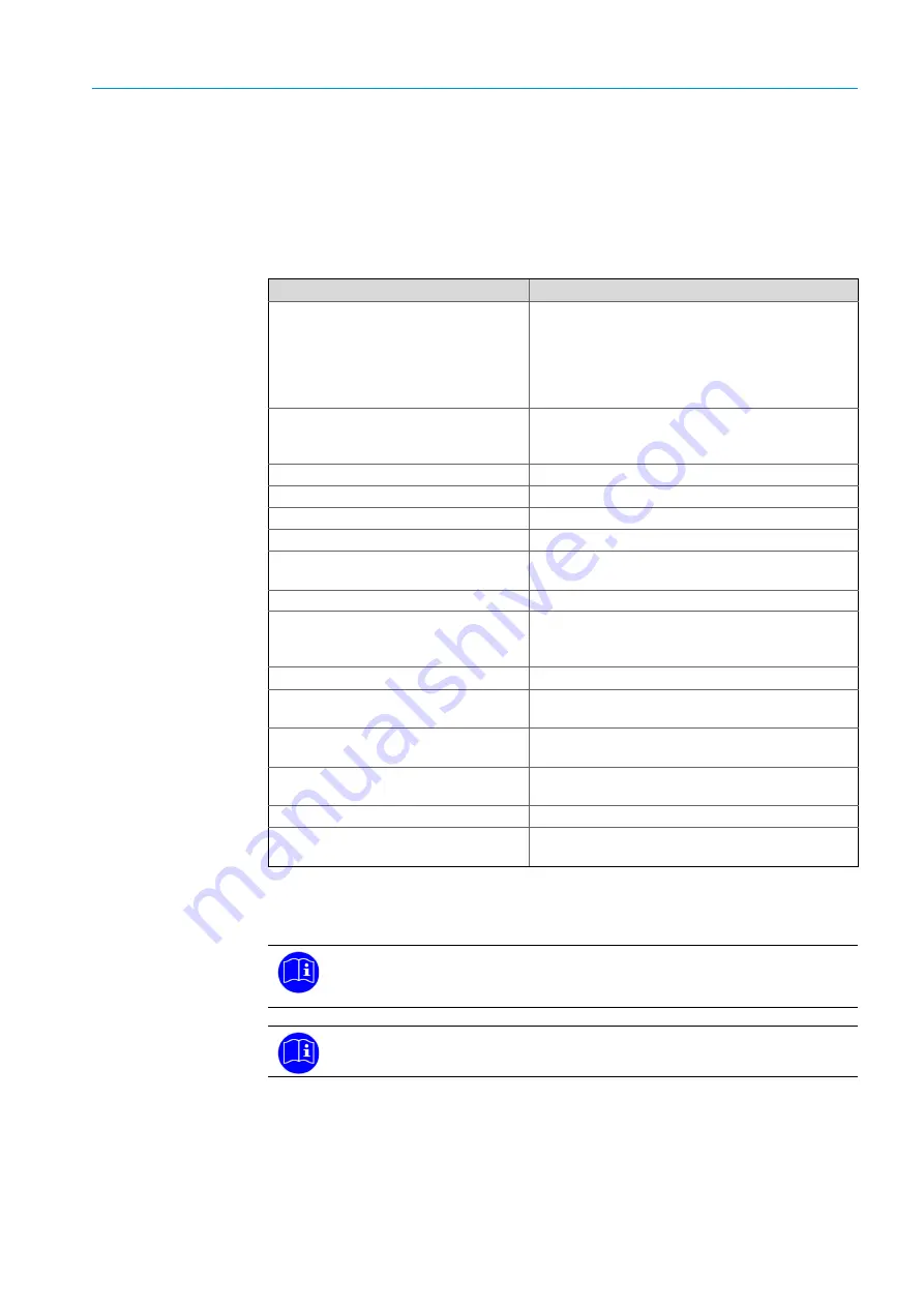
see following Table.

System component to be checked

Check for:

Lines/hoses

– Condensate residues

– Blockage

– Contamination

– Cracks

– Porous or brittle material

– Tight and correct seat

Filter

[1]

– Condensate residues

– Contamination

– Ready for operation

Humidifier container

[2]

– Ready for operation

Sample gas pump

– Ready for operation

Water trap

[3]

– Condensate residues

Analyzers

– Ready for operation

NO

x

 converter (option)

– Ready for operation

– Cartridge

Gas cooler

– Ready for operation

Span gases

– Use-by  date

– Remaining reserves

– Pressures

System cabinet climate control

– Ready for operation

Gas monitor / Gas measurement 

computer

– Ready for operation

Condensate collector

(with level switch)

– Ready for operation

– Fill level

Sample gas outlet, sample gas recircu-

lation

– Blockages

Sampling probe

– Ready for operation

External components and signal 

generators

– Ready for operation

[1] Possibly replace filter elements/inserts

[2] Fill, if necessary

[3] Replace the water trap when condensate is present

System components to be checked prior to commissioning

In addition to this list, also observe the information and conditions for particular 
system components in Sections “Commissioning” and “Maintenance” in these 
Operating Instructions.

Refer to the Operating Instructions for the individual system components for 
further details and information.

Summary of Contents for PowerCEMS100

Page 1: ...MMMI MMMOPERATING INSTRUCTIONS OPERATI NG INSTRUCTIO NS PowerCEMS100 Customer specific Analysis System Installation Operation Maintenance Title Page...

Page 2: ...CK AG Nimburger Str 11 D 79276 Reute Germany Legal Information This work is protected by copyright Any rights derived from the copyright shall be reserved for SICK AG Reproduction of this document or...

Page 3: ...use 13 2 9 Requirements on the personnel s qualification 13 3 Product description 15 3 1 Features of the PowerCEMS100 15 3 2 Method of operation 15 3 3 Functional principle 15 3 4 Internal functional...

Page 4: ...ampling probe 34 6 9 Restarting after longer shutdown 35 7 Operation 37 7 1 Operating the system components 37 7 2 Layout and functions of system components 37 7 3 System parameters 37 7 4 Operating e...

Page 5: ...4 Maintenance intervals 51 10 5 Cleaning information 53 10 6 Wear parts WP Spare parts SP 53 10 7 External components Wear parts WP Spare parts SP 58 11 Troubleshooting 59 11 1 Important Information...

Page 6: ...CONTENT 6 8019897 V2 0 2017 12 SICK O P ERA TI N G I NS TRU CT IO N S PowerCEMS100 Subject to change without notice...

Page 7: ...document contains Information necessary during the life cycle of the PowerCEMS100 must be made available to all persons working with the system Read this document carefully and ensure that the content...

Page 8: ...stem control BCU with operator panel Operating Instructions Data Sheets for components of the control cabinet climate con trol and lighting optional Cabinet cooling unit Cabinet fan Control cabinet li...

Page 9: ...on the Pow erCEMS100 Only qualified persons from the respective departments are permitted to work on the PowerCEMS100 Follow the business procedures Follow the local rules Follow the local rules with...

Page 10: ...voltage Warning of explosive atmosphere Warning of explosive substances Warning of inflammable substances Warning of oxidizing substances Warning of toxic substances Warning of acidic substances Warn...

Page 11: ...val document legal specifications as well as the T V performance test DANGER TOXIC GASES Danger of intoxication by inhalation Serious injuries or death Operate the system in adequately vented areas or...

Page 12: ...ath Never stand under suspended loads Special attention when lifting the loads Comply with the lifting instructions to prevent head injuries and other accidents Use suitable lifting equipment Wear pro...

Page 13: ...taken at a sampling point and fed through the analysis system extractive measurement Any warranty claim against SICK AG becomes void when the product is used for any other purpose or is modified 2 9 R...

Page 14: ...14 8019897 V2 0 2017 12 SICK O P ERA TI N G I NS TRU CT IO N S PowerCEMS100 Subject to change without notice 2 FOR YOUR SAFETY...

Page 15: ...duct using a gas sampling probe and fed to the analysis system via a heated controlled or self limiting sample gas line Refer to the Technical System Documentation for individual system specific equip...

Page 16: ...gas cooler with optional Flowmeter Needle valve Condensate pump Filter Humidity sensor Sample gas filter option Condensate collection container with level monitor Water trap Sample gas monitoring flo...

Page 17: ...measuring components 3 7 Interfaces Measured value status and control outputs Measured value outputs analog freely selectable 0 2 4 20 mA linear Status and control outputs Measured value and control...

Page 18: ...0 Exterior view of front panel without cooling unit Legend 1 Air inlet optionally fitted cooling unit on the side 2 Main power switch 3 Status indicators Measuring Maintenance Failure 4 BCU operator p...

Page 19: ...t Legend 1 Condensate container 2 Sample gas cooler 3 Gas analyzers 4 BCU signal unit 5 Terminal strips fuses relays 6 BCU operator panel rear 7 Temperature controller for sample gas lines 8 Flue gas...

Page 20: ...20 8019897 V2 0 2017 12 SICK O P ERA TI N G I NS TRU CT IO N S PowerCEMS100 Subject to change without notice 3 PRODUCT DESCRIPTION 3 9 Gas flow plan Fig 4 PowerCEMS100 gas flow plan...

Page 21: ...e gas cooler 8RM1 Non return valve 8GQ1 Sample gas pump 8KH4 Sample gas test gas valve 8KH2 8KH3 8KH5 8KH6 8KH7 8KH8 Test gas valves 8KH9 Test gas vent valve 8KH1 Test gas feed valve for test gas feed...

Page 22: ...22 8019897 V2 0 2017 12 SICK O P ERA TI N G I NS TRU CT IO N S PowerCEMS100 Subject to change without notice 3 PRODUCT DESCRIPTION...

Page 23: ...mbled and delivered in separate packing in the control cabinet Note The system may only be transported and installed by qualified persons The device may only be installed and operated by skilled techn...

Page 24: ...24 8019897 V2 0 2017 12 SICK O P ERA TI N G I NS TRU CT IO N S PowerCEMS100 Subject to change without notice 4 TRANSPORT...

Page 25: ...o not block air outlet of the system control cabinet ventilation and climate control Provide individual attachments for the system cabinet For installation on gratings provide a base plate under the s...

Page 26: ...the top of the system cabinet Note Observe local regulations on installing gas cylinders Provide a suitable installation location for the pressure control unit WARNING HAZARD BY HOT SURFACES ON THE CO...

Page 27: ...PLE GASES Serious injuries of the respiratory system Lead the measuring system gas outlets outdoors or into a suitable flue Protect sample gas outlet against frost Sample gas must not penetrate the in...

Page 28: ...nd the gas path is leaky dilution effect At the sample gas outlet no significant counter pressure may built up and no strong pressure fluctuations may occur Make sure sample gas can flow out freely wi...

Page 29: ...or system supply auxiliary power match the system specific specifications of the PowerCEMS100 analysis system 5 6 External components and signal generators Carry out electrical and mechanical connecti...

Page 30: ...30 8019897 V2 0 2017 12 SICK O P ERA TI N G I NS TRU CT IO N S PowerCEMS100 Subject to change without notice 5 INSTALLATION...

Page 31: ...d for tight seat All project specific external components and signal generators to be integrated such as Sample gas probes Sample gas lines Temperature sensors Pressure sensor or other external signal...

Page 32: ...of possible drift and compliance with switch on conditions 6 4 Commissioning of sample gas cooler Wait for the cooler warm up phase to end duration approx 30 minutes A green LED on the display signals...

Page 33: ...nned installation location local conditions The following can be used for example Control cabinet fan option Control cabinet cooling unit option Control cabinet heating option The climate components a...

Page 34: ...ampling probe to end duration approx 2 hours Check the setpoint setting on the built in thermostat or on the external controller optional controlled heater Make sure the built in ball valve is closed...

Page 35: ...residues Analyzers Ready for operation NOx converter option Ready for operation Cartridge Gas cooler Ready for operation Span gases Use by date Remaining reserves Pressures System cabinet climate cont...

Page 36: ...36 8019897 V2 0 2017 12 SICK O P ERA TI N G I NS TRU CT IO N S PowerCEMS100 Subject to change without notice 6 COMMISSIONING...

Page 37: ...Operating Instructions of the individual system components Refer to the Technical System Documentation for layout of the individual system components in the PowerCEMS100 analysis system Refer to the O...

Page 38: ...phase the start process is saved in the logbook Measure is displayed in the status bar at the end of the heating up phase Check safe operating state Signal LED POWER lights red Signal LED FAILURE does...

Page 39: ...Analog outputs AOi Source Zero Ranges o Modbus inputs MBIi Signal Modbus output MBOi Source o Formulas Formulas Programming Activating o Function button Name Function o o Timer Cyclic trigger CTi Nam...

Page 40: ...meter upload Firmware update Maintenance mode Activate status flag o Status display o o Function buttons Start a function o o Operator commands Start abort an adjustment validation function Manual adj...

Page 41: ...th this test gas This actual value is then compared against the programmed setpoint value The internal adjustment parameters are then corrected mathematically so that the actual value then corresponds...

Page 42: ...st gas pressure The test gas pressure for both adjustment procedures is set to 1 3 bar for all test gases Setting is done via the pressure control valve 8 5 Flow rate values The flow rate values for b...

Page 43: ...dgment The maintenance request is reset 8 6 3 Manual adjustment abort on the analyzer After a manual adjustment abort the adjustment values are discarded Maintenance request is not activated Malfuncti...

Page 44: ...44 8019897 V2 0 2017 12 SICK O P E R A T I N G I N S TR UC TI O N S PowerCEMS100 Subject to change without notice 8 ADJUSTING...

Page 45: ...king the application and ambient conditions For purging suction in the ambient air via the sample gas probe for several minutes Stop the purge gas feed and close off all gas connections of the PowerCE...

Page 46: ...s 20 55 C Relative humidity 75 without condensate Note Observe the minimum switch off times for the control cabinet cooling unit Non observance of the minimum switch off times can damage the control c...

Page 47: ...ironment regulations end guide lines for disposal of industrial and electronic waste WARNING TOXIC CONDENSATE Serious damage to environment and nature The liquid contained in the condensate container...

Page 48: ...48 8019897 V2 0 2017 12 SICK O P E R A T I N G I N S TR UC TI O N S PowerCEMS100 Subject to change without notice 9 DECOMMISSIONING...

Page 49: ...n by the manufacturer Otherwise the manufacturer s warranty becomes void the approval becomes void DANGER SYSTEM SWITCHED ON Serious injuries or death Prior to opening disconnect the system cabinet fr...

Page 50: ...gas signals are not processed 10 3 Visual inspection functional check Perform outer visual check daily weekly Pay attention to the signal lamps on the system cabinet door Check the following component...

Page 51: ...media replace ment Inlet outlet must be free X Humidifier con tainer option Check function Check liquid reserves solution and or distilled water of humidifier container and top up if necessary Fillin...

Page 52: ...f the condensate pump depending on the wear Check screw connections connections Note Observe the Operating Instructions of the sample gas cooler and the condensate pump Caution The condensate can be a...

Page 53: ...SP Require ment per x years Filter diaphragm made of glass fiber 55 mm diameter Sales unit 25 pcs 5 312 005 Front fitted filter FI56NK3 2028590 ext filter X 1 pc 1 y Brass wool approx 12 g 2 028 844 C...

Page 54: ...c 5 312 360 Aerosolfilter CLF 5 W 5311436 X 1 pc 1 y Adsorption pad filter FT AP 03F5200 M C 5 322 648 X 1 pc 2 y Adsorption material for adsorption pad dry beads with moisture indicator silica gel Co...

Page 55: ...Require ment per x years Humidifier container complete FP BF G1 4 03F5700 5 320 642 X As required Washing bottle complete option FP W G1 4 03F5300 5 311 644 X As required Washing bottle complete optio...

Page 56: ...M X 1 pc 1 y Heat conductive paste 50 g 5 310 689 Sample gas cooler ECM X 1 pc 1 y Sample gas cooler AGT MAK10 6 029 673 Description Part No used in WP SP Require ment per x years Spare filter cartrid...

Page 57: ...c 3 y Sample gas pump complete B hler P2 3SP 6 032 166 X 1 pc 3 y Sample gas pump complete B hler P2 3SP V 6 026 333 X 1 pc 3 y Sample gas pump B hler P1 1 Description Part No used in WP SP Require me...

Page 58: ...ste for heating cartridge insertion 5 601 324 Gas sampling probe SP210 H X 1 pc 1 y Sample gas probe SP2000 SP2000 H R Description Part No used in WP SP Require ment per x years Parts set SP2oo0 compr...

Page 59: ...Possible causes Action Cabinet temperature too high Fan failure Check fan Cooling unit failure Check cooling unit Thermostat defective Replace thermostat Test gas flow too low Test gas bottle empty or...

Page 60: ...inished Wait for warm up phase to finish Depending on components to be measured measuring ranges and drift the warming up phase takes up to 24 hours Test gas and set test gas concentra tion do not mat...

Page 61: ...Ox converter option function monitoring Query of setpoint value operating temperature Sample gas cooler function monitoring Query of setpoint value operating temperature Level sensor in condensate col...

Page 62: ...62 8019897 V2 0 2017 12 SICK O P ERA TI N G I NS TRU CT IO N S PowerCEMS100 Subject to change without notice 11 TROUBLESHOOTING...

Page 63: ...ing all applicable modifications and is based on the relevant harmonized standards and or specifications EU Directives Low Voltage Directive 2006 95 EC Electromagnetic Compatibility 2004 108 EC Applie...

Page 64: ...C Ambient humidity 75 Relative humidity non condensing Compliance Approved for plants requiring approval 2001 80 EC 13th BimSchV 2000 76 EC 17th BimSchV 2006 95 EC Low Voltage Directive 2008 108 EC El...

Page 65: ...tion Versions with cooling unit or heating option Weight 250 kg 350 kg Depending on version Observe load capability of roofs floors Installation In buildings with protection against corrosive atmosphe...

Page 66: ...support sick jp Malaysia Phone 603 8080 7425 E Mail enquiry my sick com Mexico Phone 52 472 748 9451 E Mail mario garcia sick com Netherlands Phone 31 0 30 229 25 44 E Mail info sick nl New Zealand Ph...

Reviews: