Operating instructions
Chapter
6
ICR 84x Image Code Reader
Operation
8 010 961/0000/10-05-2005
©
SICK AG · Division Auto Ident · Germany · All rights reserved
6-5
Preparations:
1.
Connect the ICR to the SICK CDB 420 or CDM 420 Connection Module.
2.
Connect the reading pulse sensor (e.g. photoelectric reflex switch) to the “Sensor 1“
switching input of the ICR via the CDB 420 or CDM 420 (see
the “Sensor 1“ switching input“, Page 5-13
3.
Switch on the power supply to the CDB 420 or CDM 420.
The ICR beeps when it has been started and the self-tests have been successfully com-
pleted. It beeps twice when reading mode is initiated. The “Device Ready“ LED lights up.
4.
Connect the PC to the ICR (see
Chapter 5.5.6 “Connecting the Ethernet interface“,
).
When the green “Ready“ LED at the RJ-45 socket of the ICR lights up, a physical
connection been successfully established.
5.
Install the CLV Setup program on the PC (see
Chapter 10.3 “Installation and operating
instructions for the PC-based “CLV Setup“ program“, Page 10-3
) and start the program.
Starting the Setup Assistant and calling up the Connection Assistant
1.
In the program window of CLV Setup, click
in the tool bar or select CLV A
SSISTANT
in
the T
OOL
menu.
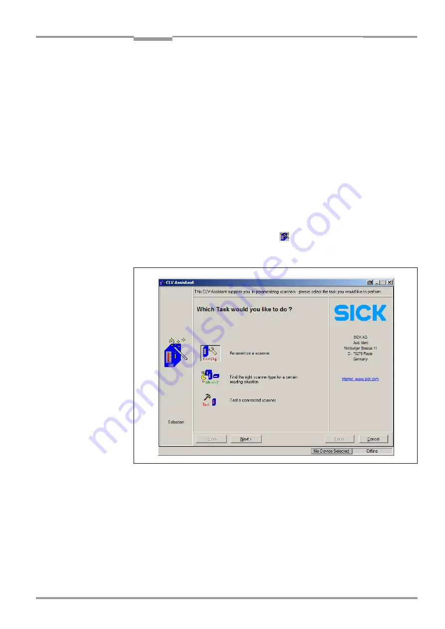
The Assistant displays with the following dialog box:
The program window of CLV Setup is minimized.
2.
Confirm the default “Parametrize a scanner“.
To do so, click N
EXT
.
The dialog box of the
Connection Assistant
is then displayed (
Fig. 6-3:
CLV Assistant: Starting up window


