Operating Instructions
Chapter
4
CLV 42x bar code scanner
Installation
8 009 981/O078/16-08-2004
©
SICK AG · Division Auto Ident · Germany · All rights reserved
4-9
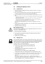
1.
Activate the operating mode as described in
Chapter 6.5.3 Adjusting mode, Page 6-18
.
2.
Position the CLV in such a way that the center of the scan line (indicated by the end of
the visible scan line, code position CP = 50) is located at the center of the bar code, or
at the center of the field for all codes if several bar codes are used.
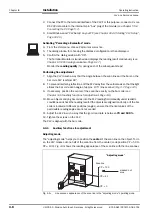
Show CP-limits
The "Show CP-limits" operating mode enables you to test whether a limit placed on the
active evaluation range of the scan line via parameterization has had the desired effects.
For this purpose, the CLV alternately masks out a certain part of the scan line corresponding
to the selected minimum and maximum values of the code position.
For information on calling up this operating mode and for checking procedures, see
Chapter 6.5.4 Show CP-limits, Page 6-19
4.4
Installing external components
4.4.1
Installing the CDB 420 or CDM 420 connection module
1.
Install the CDB 420 or CDM 420 connection module near the CLV. The distance
between the CDB 420 or CDM 420 and CLV must not exceed 10 m (32.8 ft).
2.
Install the CDB 420 or CDM 420 in such a way that the device can be accessed when
opened. The terminal interface of the CLV is accessed via the internal "Aux" connector.
Detailed information on the installation and electrical installation procedures is provided in
the
“CDB 420 Connection Module“ Operating Instructions (order no. 8 010 001,
German/English version)
respectively in the
“CDM 420 Connection Module“ Operating
Instructions (order no. 8 010 004, German/English version).
4.4.2
Installing the external reading pulse sensor
If the CLV is triggered by an external reading pulse sensor, the sensor must be mounted in
the vicinity of the CLV. The "Sensor 1" switching input is selected as the default trigger
source for this trigger type.
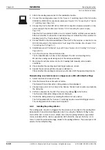
shows two examples of where a photoelectric reflex switch can be installed. This
depends on the distance a from the bar code to the front edge of the object. Depending on
the application, you may need to attach the sensor in such a way that bar codes on objects
of different sizes can be read completely during the reading interval.
Fig. 4-10:
Line scanner: installation example for the external reading pulse sensor
a
b
b < a
a
b
b < a
Bar code in the middle or at the end of the moved object
Bar code at the beginning of the moved object


