background image


18 


Spectral M3000 Zoom Q4 MKII IP65 

Product code: 43548 


DMX Cables 

Shielded twisted-pair cables with 3-pin/5-pin XLR connectors must be used for reliable DMX connection. 
You can purchase DMX cables directly from your Highlite International dealer or make your own cables. 

If you use XLR audio cables for DMX data transmission, this may lead to signal degradation and unreliable 
operation of the DMX network. 

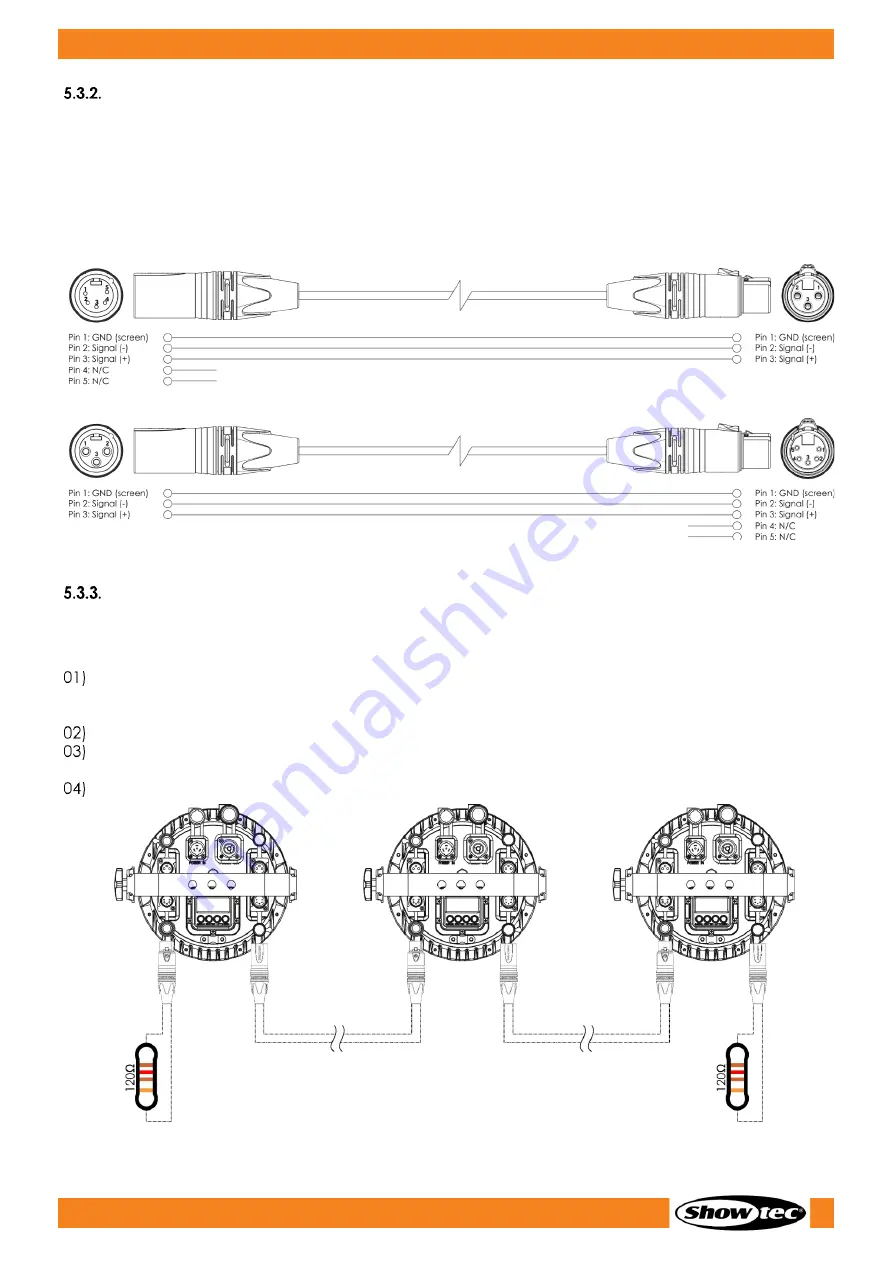
When you make your own DMX cables, make sure that you connect the pins and wires correctly as 
shown in Fig. 10. 


Fig. 10 


Master/Slave Setup 

The Spectral M3000 Zoom Q4 MKII IP65 supports master/slave control mode. To connect multiple devices 
in a master/slave setup, follow the steps below: 


Connect the first device’s DMX OUT connector to the second device’s DMX IN connector with a 
3-pin/5-pin DMX cable. The first connected device in the setup will be automatically recognized as 
the master device. 


Repeat step 1 to connect all devices as shown in Fig. 11. 


Set all subsequent devices in the setup as slave devices. See 6.6.3 Run Mode on page 25 for more 
information. 


Connect a DMX terminator (120 Ω resistor) to the DMX OUT connector of the last device in the setup. 


Fig. 11 

Summary of Contents for 43548

Page 1: ...Spectral M3000 Zoom Q4 MKII IP65 Highlite International B V Vestastraat 2 6468 EX Kerkrade the Netherlands Product code 43548 Firmware version 2 0 5 USER MANUAL ENGLISH V3 ...

Page 2: ...of the device Non observance of the instructions in this user manual may result in serious injuries and damage of property 2022 Showtec All rights reserved No part of this document may be copied published or otherwise reproduced without the prior written consent of Highlite International Design and product specifications are subject to change without prior notice For the latest version of this doc...

Page 3: ...tion 13 Personal Protective Equipment 13 Installation Site Requirements 13 Rigging 14 Angle Adjustment 15 Connecting to Power Supply 16 Power Linking of Multiple Devices 16 5 Setup 17 Warnings and Precautions 17 Stand alone Setup 17 DMX Connection 17 DMX 512 Protocol 17 DMX Cables 18 Master Slave Setup 18 DMX Linking 19 DMX Addressing 19 6 Operation 20 Safety Instructions for Operation 20 Control ...

Page 4: ...nels AR1 D 4 channels ARC 2 4 channels 33 TOUR 12 channels TR16 17 channels 33 RDM Information 35 RDM Details 35 Supported RDM PIDs Parameter IDs 35 7 Troubleshooting 36 8 Maintenance 37 Safety Instructions for Maintenance 37 Preventive Maintenance 37 Basic Cleaning Instructions 37 Draining Condensation Water 38 Corrective Maintenance 38 9 Deinstallation Transportation and Storage 39 Instructions ...

Page 5: ...ed use is regarded as non intended and incorrect use Product Lifespan This device is not designed for permanent operation Disconnect the device from the electrical power supply when the device is not in operation This will reduce the wear and will improve the device s lifespan LEDs Lifespan The light output of the LEDs gradually decreases over time lumen depreciation High operating temperatures co...

Page 6: ...important information for the correct operation and use of the product Important Read and observe the instructions in this document Electrical hazard Provides important information about the disposal of this product Symbols on the Information Label This product is provided with an information label The information label is located on the mounting bracket of the device The information label contain...

Page 7: ... before service and maintenance and when the device is not in use DANGER Electric shock caused by short circuit This device falls under IEC protection class I Make sure that the device is electrically connected to ground earth Connect the device only to a socket outlet with ground earth connection Do not cover the ground earth connection Do not bypass the thermostatic switch or fuses Do not let th...

Page 8: ...y cracks or deep scratches Contact your Highlite International dealer for more information as servicing can be performed only by instructed or skilled persons If the device is dropped or struck disconnect the device from the electrical power supply immediately If the device is exposed to extreme temperature variations e g after transportation do not switch it on immediately Let the device reach ro...

Page 9: ...e Requirements for the User This product may be used by ordinary persons Maintenance may be carried by ordinary persons Installation and service shall be carried out only by instructed or skilled persons Contact your Highlite International dealer for more information Instructed persons have been instructed and trained by a skilled person or are supervised by a skilled person for specific tasks and...

Page 10: ...e for in and outdoor applications Each function including its 0 100 dimmer 0 20 Hz strobe and colour mixing engine is controllable via DMX and Master Slave in either Manual and Auto run mode A compact and lightweight 8 4 kg design with IP65 rating makes the Spectral M3000 Q4 MKII fit for almost any environment Front View Fig 02 01 14 x 4 in 1 12W RGBW LED 02 Mounting brackets with inclination scre...

Page 11: ...al connector IN Special IP powerCON True1 connector 100 240V IN Protective valve Special IP powerCON True1 connector 100 240V OUT Special IP 3 pin DMX signal connector OUT Special IP 5 pin DMX signal connector OUT Safety eye 4 digit LED display menu buttons Special IP 5 pin DMX signal connector IN ...

Page 12: ...annels TOUR 12 channels ARC 1 3 channels AR1 D 4 channels ARC 2 4 channels AR2 D 5 channels AR2 S 6 channels HSV 3 channels TR16 17 channels AR2 Z 7 channels Control panel 4 digit LED display and buttons Connections Power connections IP65 rated Seetronic power connectors IN OUT Data connections IP65 rated 3 pin DMX connectors IN OUT IP65 rated 5 pin DMX connectors IN OUT Signal pinouts 3 pin pin 1...

Page 13: ...12 Spectral M3000 Zoom Q4 MKII IP65 Product code 43548 Dimensions Fig 06 ...

Page 14: ... and local safety regulations concerning rigging and trussing Personal Protective Equipment During installation and rigging wear personal protective equipment in compliance with the national and site specific regulations Installation Site Requirements The device can be used outdoors The device can be mounted to a truss or other rigging structure in any orientation The minimum distance between the ...

Page 15: ...e device follow the steps below 01 Use a clamp to attach the device to the supporting structure as shown in Fig 08 Make sure that the device cannot move freely 02 Secure the device with a secondary suspension for example a safety cable Make sure that the secondary suspension can hold 10 times the weight of the device If possible the secondary suspension should be attached to a supporting structure...

Page 16: ...he device with the 1 adjustment screw 03 Turn the adjustment screw 03 counterclockwise to release it 02 Tilt the device at the desired angle see Fig 09 03 Turn the adjustment screw 03 clockwise to tighten it Make sure that the device cannot move freely after the adjustment screw 03 is tightened Fig 09 ...

Page 17: ...r the device Make sure that the cable run is not too heavy A heavy cable run can cause damage to the connectors If the connectors are damaged their ingress protection IP can deteriorate Power Linking of Multiple Devices This device supports power linking Power can be relayed to another device via the power OUT connector Note that the input and the output connectors have different designs one type ...

Page 18: ...information about the control modes refer to 6 2 Control Modes on page 20 DMX Connection DMX 512 Protocol You need a DMX serial data link to run light shows of one or more devices using a DMX 512 controller or to run synchronized shows of two or more devices set in a master slave control mode The Spectral M3000 Zoom Q4 MKII IP65 has 3 pin 5 pin DMX signal IN and OUT connectors The pin assignment i...

Page 19: ...res correctly as shown in Fig 10 Fig 10 Master Slave Setup The Spectral M3000 Zoom Q4 MKII IP65 supports master slave control mode To connect multiple devices in a master slave setup follow the steps below Connect the first device s DMX OUT connector to the second device s DMX IN connector with a 3 pin 5 pin DMX cable The first connected device in the setup will be automatically recognized as the ...

Page 20: ...correctly The Spectral M3000 Zoom Q4 MKII IP65 has 9 personalities TOUR 12 channels ARC 1 3 channels AR1 D 4 channels ARC 2 4 channels AR2 D 5 channels AR2 S 6 channels HSV 3 channels TR16 17 channels AR2 Z 7 channels If you want to connect multiple devices on one data link and use them in 17 channel mode for example follow the steps below Set the starting address of the 1st device on the data lin...

Page 21: ...c colors Master Slave Auto operation mode auto programs custom programs manual operation mode static colors DMX 512 9 channel modes 3 3 4 4 5 6 7 12 and 17 channels For more information about how to connect the devices refer to 5 Setup on pages 17 19 To operate the device manually as a stand alone device or in a master slave setup 01 Adjust the intensity values for the colors See 6 6 1 Static Colo...

Page 22: ...button to open the main menu or to exit the current submenu and return to the main menu Use the UP DOWN buttons to navigate through the menus or to increase decrease numeric values Use the ENTER button to open the desired menu to confirm your choice or to set the currently selected value Start up Upon start up the display shows a splash screen with the currently installed firmware version Afterwar...

Page 23: ...22 Spectral M3000 Zoom Q4 MKII IP65 Product code 43548 Menu Overview ...

Page 24: ...Settings Display lock Calibration menu Zoom settings Calibration menu 01 Press the UP DOWN buttons to navigate through the main menu 02 Press the ENTER button to open the submenus Note Some of the submenus require a password The default password is pressing the UP DOWN buttons in the following order UP DOWN UP DOWN If you turn off the display lock this will not affect the submenus which by default...

Page 25: ...M Adjust the zoom The adjustment range is 0 255 from narrow angle to wide angle STROBE Add strobe effect The adjustment range is 0 25 from OFF to high frequency Press the ENTER button to set the value and to move to the next setting Auto Programs In this menu you can select a built in auto program or a custom program There are 10 built in auto programs which cannot be edited and 10 custom programs...

Page 26: ...nt range depends on the selected DMX channel mode TOUR 12 channels 001 501 ARC 1 3 channels 001 510 AR1 D 4 channels 001 509 ARC 2 4 channels 001 509 AR2 D 5 channels 001 508 AR2 S 6 channels 001 507 HSV 3 channels 001 510 TR16 17 channels 001 496 AR2 Z 7 channels 001 506 02 Press the ENTER button to save the changes Personality In this menu you can select the DMX channel mode 01 Press the UP DOWN...

Page 27: ...adjustment range is 0 255 from low to high intensity BLUE Set the intensity of the blue color The adjustment range is 0 255 from low to high intensity WHITE Set the intensity of the white color The adjustment range is 0 255 from low to high intensity ZOOM Adjust the zoom The adjustment range is 0 255 from narrow angle to wide angle STROBE Add strobe effect The adjustment range is 0 25 from OFF to ...

Page 28: ...o select one of the following 7 options UPLOAD See 6 6 7 1 Upload RESET See 6 6 7 2 Reset DIMMER See 6 6 7 3 Dimmer DMX ERROR See 6 6 7 4 DMX Error ZOOM See 6 6 7 5 Zoom settings CURV See 6 6 7 6 Dimming curve settings PWM See 6 6 7 7 PWM Rate 04 Press the ENTER button to confirm the selection Upload In this submenu you can export the custom programs from the master device to the connected slave d...

Page 29: ...eed Select DIMMER and press the ENTER button to open the submenu Press the UP DOWN buttons to choose one of the following options OFF linear dimmer DIM1 DIM 4 Dimmer speed from fast to slow Press the ENTER button to confirm your choice DMX Error In this submenu you can determine the behavior of the device in case of a DMX failure 01 Press the UP DOWN buttons select one of the following 2 options S...

Page 30: ...NTER button to confirm the selection PWM Rate In this submenu you can set the PWM Pulse Width Modulation frequency Select PWM RATE and press the ENTER button to open the submenu Press the UP DOWN buttons to choose the desired PWM frequency The available options are 600 Hz 1200 Hz 2000 Hz 2400 Hz 4000 Hz 6000 Hz and 25000 Hz Note The higher the PWM frequency the lower the dimmer s grayscale Press t...

Page 31: ...ion WHITE See 6 6 9 1 White Calibration 04 Press the ENTER button to confirm the selection White Calibration In this submenu you can calibrate each predefined color temperature for the white light There are 11 predefined white colors You can access these 11 colors in DMX mode See 6 7 DMX Channels on pages 32 34 for more information 01 Press the UP DOWN buttons to select one of the following 11 opt...

Page 32: ... preset positions Press the UP DOWN buttons to select one of the following 2 options POS1 POS2 02 Press the ENTER button to confirm the selection and open the submenu 03 Press the UP DOWN buttons to increase decrease the values ZOOM POSITION Set the zoom position The adjustment range is 0 255 from OFF to full zoom ...

Page 33: ... 4 4 White 4 5 5 5 Shutter Strobe 6 Zoom 6 Zoom Reset 7 Function 12 channels TOUR 17 channels TR16 Dimmer 1 1 Dimmer fine 2 Red 2 3 Red Fine 16 bit 4 Step Time If CH8 set 141 255 2 Green 3 5 Green Fine 16 bit 6 Fade Time If CH8 set 141 255 3 Blue 4 7 Blue Fine 16 bit 8 White 5 9 White Fine 16 bit 10 Macros 6 11 Shutter Strobe If CH1 2 3 4 5 set 1 255 and CH6 set 11 255 or CH8 set 41 139 7 12 Built...

Page 34: ...ity 0 100 4 4 4 Blue 000 255 From low to high intensity 0 100 5 5 5 White 000 255 From low to high intensity 0 100 6 Strobe 000 009 No function 010 255 From low to high frequency 0 25 Hz 6 Zoom 000 255 Zoom adjustment 5 45 7 Zoom Reset 000 200 No function 201 220 Zoom reset 221 255 No function Note Make sure that the Master Dimmer channel is open in order to see the light output TOUR 12 channels T...

Page 35: ...uto program 3 071 080 Auto program 4 081 090 Auto program 5 091 100 Auto program 6 101 110 Auto program 7 111 120 Auto program 8 121 130 Auto program 9 131 140 Auto program 10 141 150 Custom program 1 151 160 Custom program 2 161 170 Custom program 3 171 180 Custom program 4 181 190 Custom program 5 191 200 Custom program 6 201 210 Custom program 7 211 220 Custom program 8 221 230 Custom program 9...

Page 36: ...first 7 digits of the RDM responder ID for each model are the same The last 5 digits are different for each device Supported RDM PIDs Parameter IDs Parameter ID Value Required GET SET DISC_UNIQUE_BRANCH 0x0001 DISC_MUTE 0x0002 DISC_UN_MUTE 0x0003 COMMS_STATUS 0x0015 STATUS_MESSAGES 0x0030 STATUS_ID_DESCRIPTION 0x0031 CLEAR_STATUS_ID 0x0032 SUPPORTED_PARAMETERS 0x0050 DEVICE_INFO 0x0060 DEVICE_MODE...

Page 37: ...o DMX control The controller is not connected Connect the controller The signal is reversed The 5 pin DMX OUT of the controller does not match the DMX IN of the device Install a phase reversing cable between the controller and the device The controller is defective Try using another controller The device responds erratically to DMX control Bad data link connection Examine connections and cables Co...

Page 38: ...le depends on the conditions at the site where the device is installed When smoke or fog machines are used at the site the device will need more frequent cleaning On the other hand if the device is installed in well ventilated area it will need less frequent cleaning To establish a cleaning schedule examine the device at regular intervals during the first 100 hours of operation To clean the device...

Page 39: ...sation water collects inside the device follow the steps below to remove the condensation water Carefully remove the protective vent 13 with a wrench 16 mm Fig 14 Let the device operate at full output for 60 minutes Let the device cool down for 30 minutes Install the protective vent 13 back in place Make sure that you do not overtighten it Corrective Maintenance The device does not contain user se...

Page 40: ...h care This side up Fragile Storage Clean the device before storing Follow the cleaning instructions in chapter 8 2 1 Basic Cleaning Instructions on page 37 Store the device in the original packaging if possible 10 Disposal Correct disposal of this product Waste Electrical and Electronic Equipment This symbol on the product its packaging or documents indicates that the product shall not be treated...

Page 41: ...40 Spectral M3000 Zoom Q4 MKII IP65 Product code 43548 ...

Page 42: ...41 Spectral M3000 Zoom Q4 MKII IP65 Product code 43548 ...

Page 43: ...42 Spectral M3000 Zoom Q4 MKII IP65 Product code 43548 ...

Page 44: ... 2022 Showtec ...

Reviews: