


32
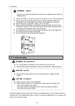
9-5. Connecting to External Fuel Tank
CAUTION
Always stop the engine, when working on the fuel line.
Always wipe any drip of Diesel fuel or oil. Do not use this equipment
when a leak is found. Repair the equipment before use.
Ensure that there is no fuel leakage on the fuel line after the fuel line
working finished.
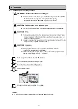
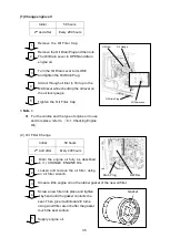
Turn the 3-way valve lever to A position.
(Installed tank use position)
Disconnect the P/T 1/2 plugs from the
External Fuel Intake and the External Fuel
Return, and then connect the hoses from
the External Fuel Tank, as shown below.
Turn the 3-way Valve Lever to B
position.
(External tank use position)
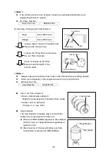
Extract the air out from the
connected hoses.
By the above procedure, it makes
possible to use an External Fuel
Tank.
< Note >
Use always oil-proof hose in 8-10mm
inner diameter as connecting hose.
The fuel level in the external fuel tank
should be 0 to 3m higher than the bottom
of the equipment. Otherwise, it may
cause engine malfunction or stoppage.
To avoid any leak from the external fuel
intake and return ports, always turn the lever for 3-way Valve to A position
whenever piping work is performed.
Use extreme caution when connecting the hoses. If the lever position is set improper,
the fuel may leak from either the Built-in Fuel Tank or the External Fuel Tank.
Set the fuel intake position 15-20mm above from the External Fuel Intake bottom line,
otherwise water or garbage in the tank may come into the fuel line.
In order to avoid engine malfunction due to air suction, set the fuel return at the same
level as the fuel intake level in the External Tank.
Refer air extraction to
『
9-2. Procedures during Operation
』
1
2
3
4
External Fuel Tank
A side Lever Position
B side Lever Position
3-way valve
External Fuel Inlet (PT1/2)
External Fuel Return (PT1/2)
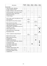
Summary of Contents for DGA50CM
Page 2: ......
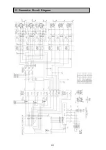
Page 50: ...46 13 Generator Circuit Diagram ...
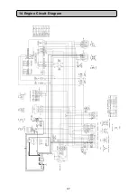
Page 51: ...47 14 Engine Circuit Diagram ...
Page 52: ... 2021 ...