background image

51

ENGLISH

• Each time these buttons are pressed, “

” and “

are moved to the corresponding DIGITAL IN.

• You should assign the connected DIGITAL INs to the desired of CD, AUX and VIDEO 1~6.

(For details, refer to “CONNECTING DIGITAL INs and OUTs” on page 7.)

Note:

• When the pure audio function is activated, the TONE CONTROL cannot be selected.

STANDBY

POWER ON

MAIN

PAGE

FAV

MUTE

CH.

SET

VOL

RETURN

DISP

MI

OSD/MENU

1

STEREO

CH/

ADJUST

2

3

4

5

6

7

8

9

0

ENT

M2

M3

DSP

DECODE

DSP

RNC-510

C D

:

A UX

:

V I D E O 1

:

V I D E O 2

:

V I D E O 3

:

V I D E O 4

:

V I D E O 5

:

V I D E O 6

:

U S B

COAX1

OPT1

OPT2

OPT3

COAX2

OPT4

OPT5

D I G I T A L     I N P U T     S E T U P

R E T U R N : B a c k                 ,     : S e l e c t

S Y S T E M                  S E T U P

R E T U R N : B a c k     E N T E R : S e l e c t  

D I G I T A L     I N P U T   S E T U P
T O NE   C O N T R O L
OS D   A U T O   D I S P L A Y :
C UR R E N T   V I D E O :  
C OMP O N E N T   V I D E O  S E T U P
D C   T R I G G E R 2   S E T U P
D I G I T A L
             R E - M A S T E R I N G :

On

VID 1

Off

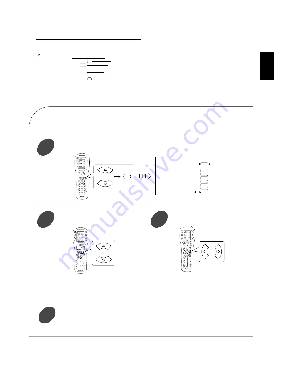
To assign the connected DIGITAL INs to the desired input sources respectively. 

To adjust the tone as desired or to select the desired cinema EQ mode.

To set the OSD AUTO DISPLAY mode as desired.

To select a video input source.

To assign the connected COMPONENT VIDEO INs to the desired of VIDEO 1~6.

To select the desired input source that uses the DC trigger 2 function.

To select the desired digital re-mastering mode.

Press the CURSOR UP(

)/DOWN(

) buttons to select the DIGITAL INPUT SETUP, then press the

ENTER button.

1

Press the CURSOR UP(

)/DOWN(

)

buttons to select the desired input source.

2

SETTING THE SYSTEM SETUP

When selecting the DIGITAL INPUT SETUP

STANDBY

POWER ON

MAIN

PAGE

FAV

MUTE

CH.

SET

VOL

RETURN

DISP

MI

OSD/MENU

1

STEREO

CH/

ADJUST

2

3

4

5

6

7

8

9

0

ENT

M2

M3

DSP

DECODE

DSP

Press the CURSOR LEFT(

)/RIGHT(

)

buttons to select the desired DIGITAL IN.

3

• Each time these buttons are pressed, the DIGITAL

INs change.

Notes:

• When you select “None” instead of a DIGITAL IN

for an input source, the analog input is automatically
selected.

• In such a case that a DIGITAL IN is assigned to two

input sources or more, when these input sources are
selected, the digital audio signals can be heard from
the same DIGITAL IN.

Repeat the above steps 

and 

until the

connected DIGITAL INs are assigned to
the desired input sources respectively.

4

STANDBY

POWER ON

MAIN

PAGE

FAV

MUTE

CH.

SET

VOL

RETURN

DISP

MI

OSD/MENU

1

STEREO

CH/

ADJUST

2

3

4

5

6

7

8

9

0

ENT

M2

M3

DSP

DECODE

DSP

RNC-510

Summary of Contents for Newcastle P-965

Page 1: ...P 965 A V Tuner Pre Amplifier...

Page 2: ...ur safety if in any doubt about the effective earthing of the power point consult a qualified electrician PAN EUROPEAN UNIFIED VOLTAGE All units are suitable for use on supplies 220 240 V AC FOR YOUR...

Page 3: ...TENING TO A PROGRAM SOURCE 22 SURROUND SOUND 25 ENJOYING SURROUND SOUND 28 LISTENING TO RADIO BROADCASTS 33 LISTENING TO RDS BROADCASTS FM only 36 RDS Tuner Regional Option for some countries in Europ...

Page 4: ...M2 OUT 3 10 7 1 8 12 9 2 5 4 3 5 11 4 10 6 System Connections Pleas be certain that this unit is unplugged from the AC outlet before making any connections Since different components often have differ...

Page 5: ...outputs them from the MONITOR OUTs Because of this one of three types of MONITOR OUT jacks can be connected to the monitor TV regardless of how the video components are connected to VIDEO IN jacks of...

Page 6: ...jacks of VIDEO 3 VIDEO 4 VIDEO 5 can also be connected to an additional video component such as a cable TV tuner an LD player or satellite system Connect the jacks of VIDEO 4 VIDEO 5 to the video comp...

Page 7: ...only supports 2 channel PCM signals In case of other digital signals loud noise or no sound may be heard from the speakers and it may be harmful to your ears and damages the speakers The digital signa...

Page 8: ...SETTING THE SPEAKER SETUP on page 46 According to speaker settings you cannot use either SURROUND BACK RIGHT jack or both of SURROUND BACK jacks For installing the speakers refer to Speaker placement...

Page 9: ...k speaker place it at the rear center facing the front at a slightly higher position 0 to 10 inches than the surround speakers We recommend installing the surround back speaker at a slightly downward...

Page 10: ...ecting the DC TRIGGER 2 SETUP on page 55 Notes This output voltage 12 V d c 100mA is for status control only it is not sufficient for drive capability When making DC TRIGGER connection you should use...

Page 11: ...ompatible component from another room with the universal remote control unit connect the IR OUT jack to the IR emitter Connecting block Multi room system kit output Another room Room 2 This unit Main...

Page 12: ...eason we recommend that it only be done by qualified installers For more information on future upgrades and external control visit the Sherwood web site at www sherwoodamerica com or contact your deal...

Page 13: ...HONE jack 25 HEADPHONE SELECTOR button 26 CHANNEL SELECTOR button 27 DOLBY PL II MUSIC PARAMETER button 28 CINEMA EQ button 29 TONE MODE button 30 ROOM 2 button 31 FM MODE button 32 PRESET UP DOWN but...

Page 14: ...TAPE MON STEREO RDS EON TA PTY MPEG PURE ANALOG DIGITAL RE MASTERING TUNED TP PRESET VIDEO SET 1 2 3 4 5 6 Z R2 MUTE CINE EQ MEMORY AP SW L C R SL SW SR SB LFE 1 2 11 12 13 14 15 16 17 18 19 3 4 5 6 7...

Page 15: ...INK connections between Sherwood components In the DIGI LINK III remote control system if pressing PLAY etc on CD player or tape deck CD or TAPE MONITOR is selected automatically on the unit without s...

Page 16: ...1 VIDEO 2 VIDEO 3 VIDEO 4 VIDEO 5 VIDEO 6 DTS DOLBY DIGITAL PCM MPEG 8 CH DIRECT 7 1 IN PL II MOVIE PL II MUSIC NEO 6 CINEMA NEO 6 MUSIC AUDIO 2 AUD2 for receiver 001 CD for CD player 001 TAPE for ta...

Page 17: ...ol V 768 etc 001 POWER ON STANDBY PLAY FORWARD SKIP REVERSE SKIP FORWARD SEARCH REVERSE SEARCH PAUSE RETURN STOP CURSOR CONTROL ENTER 0 9 DISPLAY MENU SETUP TITLE AUDIO SUBTITLE DISC SKIP OPEN CLOSE Z...

Page 18: ...TROL OPERATION RANGE Use the remote control within a range of about 7 meters 23 feet and angles of up to 30 degrees aiming at the remote sensor Remove the cover Load four alkaline batteries AAA size 1...

Page 19: ...01 SAVE EXIT DOWN UP ENTER Select the device from which the appropriate 3 digit setup code table will be selected Example If it is the AUD 1 code table select the AUD 1 6 Example The 3 digit setup cod...

Page 20: ...to enter the next setup code Notes If the Manufacturer Brand for your component is not listed in Set Up Code Table in the operating manual of this remote control please use the 2 Auto Scan Method on p...

Page 21: ...in the main room aim the universal remote control or the ROOM 2 remote control at the remote sensor of this unit Remove the cover Load two batteries AAA size 1 5V matching the polarity 21 ENGLISH ROO...

Page 22: ...d remote control refer to Universal Remote Controls on page 15 for details about operation Before operating this unit first set this unit as desired for optimum performance doing the OSD menu setting...

Page 23: ...odes cannot be selected Note When the pure audio function is activated the tone mode cannot be selected When playing back the program sources with surround sound refer to ENJOYING SURROUND SOUND on pa...

Page 24: ...g circuits are turned off Press this button again to cancel the pure audio function When you select other input source or the other between digital and analog inputs the pure audio function is automat...

Page 25: ...ion digital matrix decoder used for DTS ES Matrix 6 1 to achieve 6 1 channel surround playback DTS Neo 6 surround includes two modes for selecting the optimum decoding for the signal source DTS Neo 6...

Page 26: ...channel This mode is a surround system which faithfully reproduces the ambience and dynamics of movie soundtracks and music alike Though the number of audio channels are same as Dolby Digital discs be...

Page 27: ...r of the encoded channels etc the sound from the corresponding channels cannot be reproduced For details refer to SETTING THE SPEAKER SETUP on page 46 Channels FRONT L R CENTER SURROUND SURROUND BACK...

Page 28: ...al 2 channel sources DOLBY DIGITAL EX DOLBY DIGITAL PL II MOVIE PL II MUSIC PL II GAME DTS sources Auto DTS mode DTS ES MATRIX or DTS ES DISCRETE DTS MPEG sources Auto MPEG mode MPEG PCM 2 channel sou...

Page 29: ...tereo mode or the 2CH downmix mode is selected To cancel either the stereo mode or the 2 CH downmix mode select the desired surround mode with using the MULTI CONTROL knob or DSP MODE UP DOWN buttons...

Page 30: ...if you were in a typical listening room with moderate reverberations DOLBY HEADPHONE 3 This simulates the soundfield as if you were in a large space like theater Off It returns to the previous mode In...

Page 31: ...adjust the level as desired until the sound level of each speaker is heard to be equally loud 2 You can select the desired channel and adjust its level with repeating the steps and in Adjusting the c...

Page 32: ...from 0 to 7 Dimension control DIMENSION default value 0 This gradually adjusts the soundfield either towards the front or towards the rear The control can be set in 7 steps from 4 to 2 Adjusting the D...

Page 33: ...rocedure with using Manual tuning operation Auto presetting Manual tuning is useful when you already know the frequency of the desired transmitter Perform the steps in Auto tuning procedure and press...

Page 34: ...hould memorize them again When using the NUMERIC buttons on the remote control Examples For 3 For 15 For 30 Select the desired preset number 1 30 and press the ENTER MEMORY button 3 STANDBY POWER ON A...

Page 35: ...ON AUD2 SCH M E TA PTY S E PTY MEMO P SCA TUNE PSET TUNE PSET PAGE2 35 Listening to FM stereo broadcasts While listening to FM broadcasts Each time this button is pressed the FM mode changes as follo...

Page 36: ...ns broadcasting the traffic program TP SEARCH is displayed TP search The tuner automatically searches stations offering RDS services and the station name is displayed If the station found is not the d...

Page 37: ...no station is found NO PROGAM is displayed TUNE STANDBY POWER ON AUD2 SCH M E TA PTY S E PTY MEMO P SCA TUNE PSET TUNE PSET PAGE2 PRESET or While displaying PTY SEARCH select the desired program type...

Page 38: ...und the previous traffic program station will be tuned in Press the EON TA button to cancel the EON TA mode EON TA Each time this button is pressed the display mode changes as follows If the signals a...

Page 39: ...O 1 1 Start play on the desired input 3 or STANDBY POWER ON AUD1 TUNER VID1 CD VID2 T MON VID3 AUX VID4 PHONO VID5 PAGE1 VIDEO The audio and video signals from the desired input will be dubbed onto th...

Page 40: ...ital recording may not be available depending on the signal format There are some restrictions on recording digital signals When making digital recordings refer to the operating instructions of your d...

Page 41: ...to automatically turn off after the specified period of time Each time this button is pressed the sleep time changes and disappears in several seconds as follows 10 20 30 60 90 OFF Unit minutes While...

Page 42: ...remote control This function can be operated on the input sources except TUNER and TAPE MONITOR You can select VID 6 or 7 1 IN on the page 2 of AUD 1 on the remote control Then the next digit will fli...

Page 43: ...ed separately too For details refer to SETTING THE ROOM2 FEED SETUP on page 63 The MUTE and VOLUME UP DOWN buttons on this remote control can be available for the ROOM 2 source only Note When the muti...

Page 44: ...countries The OSD menu allows you to perform the setup procedures easily In most situations you will only need to set this once during the installation and layout of your home theater and it rarely n...

Page 45: ...K E R C O N F I G U R A T I O N S P E A K E R D I S T A N C E V I R T UA L S P E A K E R SE TU P SUBWO OF ER A C T I V E SUBWO OF ER M O D E L F E SW C R O S S O V E R F R E Q 8 0 H z 57 S URROUN D S...

Page 46: ...ACK is automaticaly set to None STANDBY POWER ON MAIN PAGE FAV MUTE CH SET VOL RETURN DISP MI OSD MENU 1 STEREO CH ADJUST 2 3 4 5 6 7 8 9 0 ENT M2 M3 DSP DECODE DSP RNC 510 S P E A K E R CON F I G UR...

Page 47: ...ECODE DSP RNC 510 Press the CURSOR UP DOWN buttons to select the unit 2 Press the CURSOR LEFT RIGHT buttons to select the desired unit 3 STANDBY POWER ON MAIN PAGE FAV MUTE CH SET VOL RETURN DISP MI O...

Page 48: ...ss the ENTER button 1 When selecting the VIRTUAL SPEAKER SETUP Press the CURSOR UP DOWN buttons to select the SPEAKER LAYOUT mode 3 Press the CURSOR LEFT RIGHT buttons to select the desired mode 4 You...

Page 49: ...CURSOR LEFT RIGHT buttons to select the desired mode 6 Each time these buttons are pressed the virtualization mode changes as follows WIDE This mode expands the front channel sound field REFERENCE Thi...

Page 50: ...es only the low Frequency Effects from multi channel sources that contain LFE channel also called the 1 channel LFE SW Select this when the subwoofer reproduces the Low Frequency Effects or the bass s...

Page 51: ...AUTO DISPLAY mode as desired To select a video input source To assign the connected COMPONENT VIDEO INs to the desired of VIDEO 1 6 To select the desired input source that uses the DC trigger 2 functi...

Page 52: ...the tone bass and treble cannot be adjusted When the tone defeat mode is set to Off to adjust the tone bass and treble 1 Press the CURSOR UP DOWN buttons to select the desired tone mode Each time thes...

Page 53: ...8 9 0 ENT M2 M3 DSP DECODE DSP Each time these buttons are pressed the mode changes as follows On To turn on the current status display Off To turn off the current status display STANDBY POWER ON MAI...

Page 54: ...the component video signals can be viewed from the same COMPONENT VIDEO IN Each time these buttons are pressed and are moved to the corresponding COMPONENT VIDEO IN You should assign the connected COM...

Page 55: ...nd VIDEO SELECTOR buttons etc the DC trigger function is automatically activated For details refer to CONNECTING DC TRIGGER OUTs on page 10 When the ENTER button is pressed at the input source marked...

Page 56: ...the CURSOR UP DOWN buttons to select the DIGITAL RE MASTERING 1 Press the CURSOR LEFT RIGHT buttons to select the desired mode 2 When selecting the DIGITAL RE MASTERING Notes The digital re mastering...

Page 57: ...equalizer operating instructions for guidance on switching off or defeating the equalizer Only when the digital input is selected as signal input for the input sources except PHONO TUNER and TAPE MON...

Page 58: ...ct the required decoding mode and the available surround mode according to the input signal format When the 8 CH DIRECT is selected as an input source the decoding and surround modes cannot be selecte...

Page 59: ...arying degrees The control can be set in 8 steps from 0 to 7 default value 0 When selecting the DIMENSION control This gradually adjusts the soundfield either towards the front or towards the rear The...

Page 60: ...call the channel levels memorized into preset memory or to memorize the channel levels adjusted in the CH LEVEL TRIM menu etc To memorize the adjusted channel levels into preset memory To adjust the c...

Page 61: ...NDBY POWER ON MAIN PAGE FAV MUTE CH SET VOL RETURN DISP MI OSD MENU 1 STEREO CH ADJUST 2 3 4 5 6 7 8 9 0 ENT M2 M3 DSP DECODE DSP RNC 510 STANDBY POWER ON MAIN PAGE FAV MUTE CH SET VOL RETURN DISP MI...

Page 62: ...h lower the setting as necessary Press the CURSOR UP DOWN buttons to select the LFE LEVEL TRIM then press the ENTER button 1 Press the CURSOR UP DOWN buttons to select the desired LFE level mode 2 Pre...

Page 63: ...and the connected amplifier the ROOM 2 speaker and the connected amplifier may be damaged Therefore be sure to set the volume mode to Fixed for safe operation when using amplifier with its own volume...

Page 64: ...ECODE DSP STANDBY POWER ON MAIN PAGE FAV MUTE CH SET VOL RETURN DISP MI OSD MENU 1 STEREO CH ADJUST 2 3 4 5 6 7 8 9 0 ENT M2 M3 DSP DECODE DSP RNC 510 Each time the CURSOR CONTROL buttons are pressed...

Page 65: ...by motors fluorescent lamps or lightning etc Batteries are not loaded or exhausted The remote sensor is obstructed DIGI LINK connections are not made properly Malfunction due to external influences su...

Page 66: ...Output level 75 Video Composite normal 1 Vp p S Video luminance signal 1 Vp p chrominance signal 0 286 Vp p Component video R Y signal 0 5 Vp p B Y signal 0 5 Vp p Y signal 1 0 Vp p FM TUNER SECTION T...

Page 67: ...P 965 5707 04747 002 0 A V Tuner Pre Amplifier...

Reviews: