Sherman digitec DIGIMIG 2OO PULSE User Manual Download Page 20


twenty 

pulse width 

The pulse width is a pulse duration, allows you to adjust the depth of penetration. The increase in width increase the depth of penetration, 
reduction reduces the amount of heat entering the material, reducing the risk of burnout of thinner plates and smaller components.

Lower values ​​of the pulse width must be used for higher currents. The greater the pulse width must be applied to small currents, a width of more than 
50% should be used for currents lower than 100A.

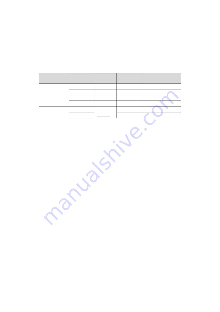
Welding machine has a built-in synergic programs for selected materials, wire diameters and shielding gases in accordance with the following table: 

Material 

designation Species 

wire 

diameter 

Shielding gas - 

recommended 

Mild steel 

Fe Co2 

0.8 / 1.0 

WHAT

 2

WHAT

 2

Fe Mix 

0.8 / 1.0 

Ar + CO

 2 (

 82/18) 

Ar + CO

 2 (

 82/18) 

Ar + CO

 2 (

 82/18) 

Aluminum 

AlMg5 

ER5356 

1.0 / 1.2 

Argon 

AlSi5 

ER4043 

1.0 / 1.2 

Argon 

stainless steel 

E308 

ER308LSi 

0.8 / 1.0 

Ar + CO

 2 (

 98/2) 

Ar + CO

 2 (

 98/2) 

Ar + CO

 2 (

 98/2) 

E316 

ER316LSi 

0.8 / 1.0 

Ar + CO

 2 (

 98/2) 

Ar + CO

 2 (

 98/2) 

Ar + CO

 2 (

 98/2) 

Argon should be used with high-class quality: 4.8 and above recommended 

In addition, depending on the operating conditions can be set inductance value, which affects the shape of the weld, the depth of penetration and the 

In addition, depending on the operating conditions can be set inductance value, which affects the shape of the weld, the depth of penetration and the 
amount of weld spatter

 . 

It should take into account the fact that the welding parameters recommended in synergy mode on conventional 

amount of weld spatter

 . 

It should take into account the fact that the welding parameters recommended in synergy mode on conventional 

amount of weld spatter

 . 

It should take into account the fact that the welding parameters recommended in synergy mode on conventional 

welding materials from the selected group and the recommended shielding gases. When welding materials of various parameters of the alloy 
may not be optimal and require adjustment settings. For this reason, the synergistic mode should not be regarded as a universal parameter 
proposal, but as a starting point for the fine adjustment of settings.

Manual SPL function MIG or manual selection of parameters is particularly useful for braze welding. Using the three welding parameters must be set 
optimal set capable of producing a proper weld. When selecting parameters to be selected low and high voltage wire feed speed. It is recommended to 
use argon as a shielding gas, but good results can also use a mixture of argon with CO

 2 (

 82/18). Due to the required shape of the weld inductance 

use argon as a shielding gas, but good results can also use a mixture of argon with CO

 2 (

 82/18). Due to the required shape of the weld inductance 

use argon as a shielding gas, but good results can also use a mixture of argon with CO

 2 (

 82/18). Due to the required shape of the weld inductance 

should be selected empirically depending on the thickness and type of material being welded. As additional material is most commonly used 
copper-based binder. These wires are labeled CuSi3 or SG -CuAl.

It is recommended to use the handle of not more than 3 m with a pad equipped with Teflon. 

8. WELDING ALUMINUM ALLOY 

In synergy mode, you can select one of two programs for aluminum welding. The programs were selected for welding wire ALSi5 type ER 4043, primarily 
intended for aluminum casting and wire AlMg5 type ER 5356, which is suitable for welding all types of constructions and profiles. Welding aluminum is 
not a simple function, the welder requires experience, knowledge and behavior of certain practices that will facilitate the welds on aluminum elements. 
Device in a synergistic adjusts the output of the corresponding grade materials and types of wires. Depending on your needs, make the appropriate 
adjustment of the voltage and the inductance to get the desired effect.

It should first of all remember a few important things that greatly affect the appearance of the joint and affect the correct welding process. 

Before starting work on the welding of aluminum components, follow these steps: 

Device: 

Ensure that the feed rollers are designed to work with aluminum groove is shaped like the letter "U" and are dedicated to the appropriate 
diameter of the welding wire. Using the wrong rollers will cause deformation of the wire and the problems in the welding process.

Summary of Contents for DIGIMIG 2OO PULSE

Page 1: ...V1 3 19 11 28 USER MANUAL WELDING RECTIFIER synergistic Inverter DIGIMIG 2OO PULSE...

Page 2: ...ing refer to the applicable health and safety regulations in the workplace During electric arc welding MIG MAG there are the following risks ELECTRIC SHOCK ARC NEGATIVE IMPACT ON HUMAN EYES AND SKIN P...

Page 3: ...the charger in a place that allows its easy handling Persons operating welder should have the power to electric welding MIG MAG know and comply with applicable health and safety regulations when perf...

Page 4: ...elf shielded flux cored wires The device allows connection of the handle Spool type gun SG which is mounted at the mini wire feed reel and D100 steel wire or colored The device is IGBT allowing a cons...

Page 5: ...g test was carried out in the ambient air temperature Duty cycle at 20 C was determined by simulation Level of security IP specifies the degree to which the device is resistant to entering of solid im...

Page 6: ...holder Spool Gun 3 Jack 4 Plug polarization changes 5 Nest 6 The power switch 7 fan 8 The connection connector shielding gas 9 The ground terminal 10 Power Cord 11 Switch handle Spool Gun 12 The wire...

Page 7: ...arefully mounted on the welded material Plug the device into a power outlet 230V 50Hz DCEN DCEP 5 1 2 Method of TIG Welding by this method it is necessary to use an additional TIG torch The handle is...

Page 8: ...e negative pole of the source 5 connected to the work piece by means of a wire with a clamp Plug the device into a power outlet 230V 50Hz the device into a power outlet 230V 50Hz 5 1 3 2 self shielded...

Page 9: ...for the wire size and type If necessary set up a proper roll For steel wire use of rollers with V shaped grooves and the aluminum wire with the groove in the U shaped 3 Place the spool of wire electr...

Page 10: ...enetration reduction reduces the amount of heat entering the material reducing the risk of burnout of thinner plates and smaller components Lower values of the pulse width must be used for higher curr...

Page 11: ...MAG modes S2T I S4T Range 50 50 INDIUM Inductance the adjustment of the arc can be optimized depending on the thickness of the work piece the method and the welding conditions Only for MIG MAG weldin...

Page 12: ...IT The only active during welding MIG MAG Pressing and holding the button will cause the flow of the shielding gas its release will end the flow of gas The synergistic modes short press the button to...

Page 13: ...f the welding current to the set value Releasing the grip will change the value of the welding current to Endi and after a time Endt will extinguish the arc and Post gas Pressing the torch will Pre ga...

Page 14: ...c After the time will stop re ignition of the arc and the cycle will continue until the button is released uchwytu Wtedy will extinguish the arc and Post gas E welded material selection button The onl...

Page 15: ...h and T right are used to control the welding parameters Rotate the knobs to the left to decrease and turning to the right to increase the parameter value Pressing the knob P will save the currently s...

Page 16: ...and additionally allows for a very high aesthetic weld face the effect of the so called scales Welding by this method is very efficient causes little deformation and at the same time allows you to get...

Page 17: ...rameter set to be loaded Changes set number can be made by turning the knob P After pressing the knob P on the display appears loaddata will be loaded and the selected set of parameters To exit load s...

Page 18: ...epth of penetration while increasing the value results in deeper penetration and the possibility of short arc welding At a set high value ARC FORCE function can be welded while maintaining the minimum...

Page 19: ...the SPL is not possible to select the base material or the diameter of the wire Welding voltage correction modes synergistic After setting the welding current modes synergistic possible to calibrate t...

Page 20: ...t as a starting point for the fine adjustment of settings Manual SPL function MIG or manual selection of parameters is particularly useful for braze welding Using the three welding parameters must be...

Page 21: ...nger period of time protect her brown wrapping paper and taped with adhesive tape Proper storage of welding wire Welding of aluminum should be stored in a clean dry environment preferably in its origi...

Page 22: ...age V V V Welding speed cm min Free outlet electrodes Mm Flow Gas l min 0 8 0 8 0 9 0 60 70 60 70 60 70 16 16 5 16 16 5 16 16 5 50 60 50 60 50 60 10 10 1 0 0 8 0 9 0 75 85 75 85 75 85 17 17 5 17 17 5...

Page 23: ...nty 15 twenty 6 1 2 45 0 45 0 230 260 24 27 230 260 24 27 230 260 24 27 230 260 24 27 230 260 24 27 45 50 45 50 45 50 twenty 15 twenty 15 twenty 15 twenty 8 9 1 2 1 6 50 0 50 0 270 380 29 35 270 380 2...

Page 24: ...speed too high Reduce the wire feed speed After power displays and LEDs are not lit No power supply Check the fuses on the network connection The fan is not working The fan was blocked folded cover St...

Page 25: ...ontact tip M6x25 TW 15 Al end of the current TW 15 M6x25 3 Contact tip M6x25 TW 15 Al end of the current TW 15 M6x25 3 The connector current TW 15 4 Gas nozzle TW 15 5 The contribution of steel 3m The...

Page 26: ...with general household waste According to the WEEE Directive Directive 2002 96 EC in force in the European Union for used electrical and electronic equipment must be used methods of utilization In Po...

Page 27: ...27 18 SCHEME ELECTRICAL...

Page 28: ...0 EU II RoHS Directive 2011 65 EU and is compliant with the following standards BS EN 60974 1 2013 04 Arc welding equipment Part 1 Welding power sources BS EN 60974 1 2013 04 Arc welding equipment Par...

Reviews: