background image

-15

Introduction

Using the Remote Control

Usable Range

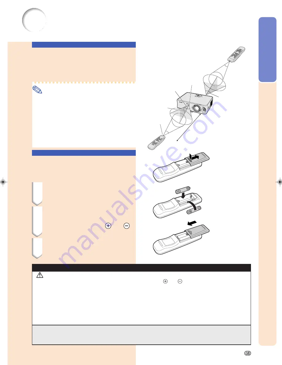
The remote control can be used to control the
projector within the ranges shown in the illus-
tration.

Note

The signal from the remote control can be re-
flected off a screen for easy operation. How-
ever, the effective distance of the signal may
differ depending on the screen material.

When using the remote control:

Be sure not to drop, expose to moisture or high
temperature.

The remote control may malfunction under a
fluorescent lamp. In this case, move the pro-
jector away from the fluorescent lamp.

Remote
control
signal
transmitters

Remote control sensor

Remote control

7 m

30

°

30

°

30

°

30

°

30

°

Inserting the Batteries

The batteries (two “AA” size) are supplied in
the package.

1

Press the 

 mark on the cover

and slide it in the direction of the
arrow.

2

Insert the batteries.

Insert the batteries making sure the po-
larities correctly match the 

 and 

marks inside the battery compartment.

3

Attach the cover and slide it until
it clicks into place.

Incorrect use of the batteries may cause them to leak or explode. Please follow the precautions below.


Caution

Insert the batteries making sure the polarities correctly match the 

 and 

 marks inside the battery compart-

ment.

Batteries of different types have different properties, therefore do not mix batteries of different types.

Do not mix new and old batteries.
This may shorten the life of new batteries or may cause old batteries to leak.

Remove the batteries from the remote control once they have run out, as leaving them in can cause them to leak.
Battery fluid from leaked batteries is harmful to skin, therefore be sure to first wipe them and then remove them
using a cloth.

The batteries included with this projector may run down in a short period, depending on how they are kept. Be
sure to replace them as soon as possible with new batteries.

Remove the batteries from the remote control if you will not be using the remote control for a long time.

XV_Z10E_E_p08_15.p65

03.11.7, 4:14 PM

15

Summary of Contents for XV-Z10E

Page 1: ... 68 ESPAÑOL 1 68 ITALIANO 1 68 NEDERLANDS 1 68 PROJECTOR PROJEKTOR PROJECTEUR PROJEKTOR PROYECTOR PROIETTORE PROJECTOR XV Z10E OPERATION MANUAL BEDIENUNGSANLEITUNG MODE D EMPLOI BRUKSANVISNING MANUAL DE MANEJO MANUALE DI ISTRUZIONI GEBRUIKSAANWIJZING ...

Page 2: ...oloured blue must be connected to the terminal which is marked with the letter N or coloured black The wire which is coloured brown must be connected to the terminal which is marked with the letter L or coloured red IF YOU HAVE ANY DOUBT CONSULT A QUALIFIED ELECTRICIAN This equipment complies with the requirements of Directive 89 336 EEC and 73 23 EEC as amended by 93 68 EEC Dieses Gerät entsprich...

Page 3: ...jector please record the Serial Number located on the bottom of the projector and retain this information Before recycling the packaging please be sure that you have checked the contents of the carton thoroughly against the list of Supplied accessories on page 14 Model No XV Z10E Serial No WARNING The cooling fan in this projector continues to run for about 90 seconds after the projector enters th...

Page 4: ... CARE SEE OPERATION MANUAL DEBRANCHER LE CORDON D ALIMENTATION AVANT DE RETIRER LA VIS L INTERIEUR DU BOITIER ETANT EXTREMEMENT CHAUD ATTENDRE 1 HEURE AVANT DE PROCEDER AU REMPLACEMENT DE LA LAMPE NE REMPLACER QUE PAR UNE LAMPE SHARP DE TYPE BQC PGB10S 1 RAYONS ULTRAVIOLETS PEUVENT ENDOMMAGER LES YEUX ETEINDRE LA LAMPE AVANT DE PROCEDER A L ENTRETIEN LAMPE A HAUTE PRESSION RISQUE D EXPLOSION DANGE...

Page 5: ...displayed buttons MENU button UNDO button ENTER button ENTER button MENU button buttons How to Read this Operation Manual In this operation manual the illustration and the screen display are simplified for explanation and may differ slightly from actual display Info Indicates safeguards when using the projector For Future Reference Maintenance Troubleshooting Glossary Page 67 Pages 63 and 64 Page ...

Page 6: ...ing the Picture Display Using Different Input Signals 34 Adjustments and Settings Using the Menu Screen 36 Menu Selections Adjustments 36 Menu Selection Settings 38 Menu Items 40 Picture Adjustment 42 Adjusting the Image 42 CLR Temp Adjusting the Colour Temperature 43 Gamma Gamma Correction 43 Signal Type Signal Type Setting 44 Memory Storing and Selecting the Adjustment Settings 44 Computer Image...

Page 7: ... them paying particular attention to cords at plugs convenience receptacles and the point where they exit from the product 14 Lightning For added protection for this product during a lightning storm or when it is left unattended and unused for long periods of time unplug it from the wall outlet and disconnect the cable system This will prevent damage to the product due to lightning and power line ...

Page 8: ...ntries PC AT is a registered trademark of International Business Machines Corporation in the United States Macintosh is a registered trademark of Apple Computer Inc in the United States and or other countries All other company or product names are trademarks or registered trademarks of their respective compa nies ...

Page 9: ... a protection circuit will automatically put the projector into the standby mode This does not indicate a malfunction Remove the projec tor power cord from the wall outlet and wait at least 10 minutes Place the projector where the intake and exhaust vents are not blocked plug the power cord back in and turn on the projector This will return the projector to the normal operating condition Caution r...

Page 10: ...up and Projection Connection of the projector and the video equipment with an S video terminal is explained as an example below Page 26 Insert the batteries inside the battery compartment of the remote control See page 15 3 ON button 4 INPUT button 6 STANDBY button 5 Adjustment buttons 5 Zoom knob 5 Focus ring 5 Lens shift lever 5 HEIGHT ADJUST button 3 ON button 5 KEYSTONE button 5 Adjustment but...

Page 11: ...angle using the HEIGHT ADJUST button Correcting trapezoidal distortion using the Keystone Correction Compresses lower side Page 29 Page 27 4 Select the INPUT mode Select INPUT 2 using the INPUT button on the projector or the INPUT 2 button on the remote control On screen Display On the remote control On the projector When pressing on the projector input mode switches in order of INPUT 1 INPUT 2 IN...

Page 12: ...e Keystone Correction when in the Keystone Correction mode ENTER button For setting items selected or adjusted on the menu MENU button For displaying adjustment and setting screens Lens shift lever For adjusting the projection position by moving the lens up and down and left and right 360 RESIZE button For switching the picture display STRETCH SIDE BAR etc Remote control sensor Zoom knob For adjus...

Page 13: ...ns shipping block cannot be attached Power indicator Temperature warning indicator Lamp indicator Temperature warning indicator Lamp indicator Power indicator Maintenance indicators Power indicator Lamp indicator Temperature warning indicator Status of the lamp Green on Red on Normal Red blinks Abnormal Green on Normal Green blinks The lamp is warming up Red on Change the lamp Off Normal Red on Th...

Page 14: ...inal DVD player DTV decoder etc See page 22 Connecting the computer See page 24 INPUT 2 terminal Connecting video equipment with S video output terminal VCR DVD player etc See page 21 AUDIO INPUT terminal Connecting an audio cable Shared audio input terminal for INPUT 1 2 and 3 See pages 21 to 24 Using the Kensington Lock This projector has a Kensington Security Standard connector for use with a K...

Page 15: ...mages when connected to a computer RGB COMP button For switching the signal type RGB or Component INPUT buttons For switching to the respective input modes MENU button For displaying adjustment and setting screens Remote control signal transmitters ON button For turning the power on Adjustment buttons For selecting menu items For adjusting the Keystone Correction when in the Keystone Correction mo...

Page 16: ... You may need an adapter commercially available for connection AN C10BM 15 pin mini D sub male connector Remote control Use the power cord that corresponds to the wall outlet in your country Three RCA adapter plugs Video cable Two AA size batteries 3 RCA to 15 pin D sub cable 3 0 m Lens cap attached Extra air filter Lens shipping block attached Operation manual Power cord 1 2 3 For Europe except U...

Page 17: ...correctly match the and marks inside the battery compartment 3 Attach the cover and slide it until it clicks into place Incorrect use of the batteries may cause them to leak or explode Please follow the precautions below Caution Insert the batteries making sure the polarities correctly match the and marks inside the battery compart ment Batteries of different types have different properties theref...

Page 18: ...r Standard Setup Front Projection Place the projector at the required distance from the screen according to the desired picture size See page 17 The distance from the screen to the projector may vary depending on the size of the screen Page 17 The default setting can be used when placing the projector in front of the screen If the projected im age is reversed readjust the set ting to Front in the ...

Page 19: ...m 106 2 4 m 1 3 m 3 2 m 4 0 m 147 9 cm 15 6 cm 63 1 cm 63 1 cm 100 2 2 m 1 3 m 3 0 m 3 8 m 139 5 cm 14 8 cm 59 5 cm 59 5 cm 92 2 0 m 1 2 m 2 8 m 3 5 m 128 3 cm 13 6 cm 54 7 cm 54 7 cm 84 1 9 m 1 1 m 2 6 m 3 2 m 117 2 cm 12 4 cm 50 0 cm 50 0 cm 72 1 6 m 0 9 m 2 2 m 2 7 m 100 4 cm 10 6 cm 42 8 cm 42 8 cm 60 1 3 m 0 7 m 1 8 m 2 3 m 83 7 cm 8 9 cm 35 7 cm 35 7 cm 40 0 9 m 0 5 m 1 2 m 1 5 m 55 8 cm 5 9...

Page 20: ...ront in the PRJ Mode menu See page 51 When the mirror is placed on the audience side set to Rear in the PRJ Mode menu See page 51 Info When using a mirror be sure to carefully position both the pro jector and the mirror so the light does not shine into the eyes of the audience Audience Audience Set to Front Set to Rear Translucent screen Mirror Mirror When the image is projected from behind the tr...

Page 21: ... before making connections This projector can be connected to Video equipmeent or audio visual equipment A VCR or other audio visual equipment See page 21 A DVD player or DTV decoder See page 22 DTV is the umbrella term used to describe the new digital television system in the United States A computer using An RGB cable commercially available or sold sepa rately See page 24 An RS 232C cable null m...

Page 22: ...he rear of the projector Note The projector is put into standby mode by plugging the power cord into the wall outlet after first turning the projector off and then unplugging the power cord from the wall out let Power cord Supplied accessory Connecting the Projector to Other Devices ...

Page 23: ...ideo equipment A ø3 5 mm minijack to RCA audio cable com mercially available is required for audio input Connecting to Video Equip ment without an S video Output Terminal INPUT 3 Using a composite video cable or audio cable a VCR or other audio visual equipment can be con nected to INPUT 3 and AUDIO INPUT terminals 1 Connect the projector to the video equipment using a composite video cable 2 Conn...

Page 24: ...brella term used to describe the new digital television system in the United States 1 Connect the projector to the video equipment using the 3 RCA to 15 pin D sub cable Secure the connectors by tightening the thumbscrews 2 Connect the projector to the video equipment using a ø3 5 mm minijack to RCA audio cable commercially available Note When connecting the projector to the com ponent video equipm...

Page 25: ...for the following connection Extending the connecting cables Example 3 RCA to 15 pin D sub cable supplied Ferrite cores RCA cables commercially available Three RCA adapter plugs supplied Info Do not remove ferrite cores attached to the 3 RCA to 15 pin D sub cable ...

Page 26: ...uthorised Projector Dealer or Service Centre Depending on the computer you are using an image may not be projected unless the sig nal output setting of the computer is switched to the external output Refer to the computer operation manual for switching the computer signal output settings When using the ø3 5 mm mono audio cable the volume level will be half of when using the ø3 5 mm stereo audio ca...

Page 27: ...if your computer terminal is not correctly set up Re fer to the operation manual of the computer for details See page 57 for connection of an RS 232C cable A Macintosh adapter may be required for us ing the computer cable to connect to some Macintosh computers Contact your nearest Sharp Authorised Projector Dealer or Service Centre Info Do not connect the RS 232C cable to a port other than the RS ...

Page 28: ...indica tor illuminates green After the lamp indi cator illuminates green the projector is ready to start operation Note The lamp indicator illuminates indicating the status of the lamp Green The lamp is ready Blinking in green The lamp is warming up Red The lamp should be replaced If the projector is put into the standby mode and immediately turned on again the lamp indicator may take some time to...

Page 29: ...ceived NOT REG will be displayed The INPUT mode is not displayed when OSD Display of the Options menu is set to OFF See page 47 About the INPUT mode INPUT 1 Compo nent RGB INPUT 2 S Video INPUT 3 Video Adjusting the Volume Press or on the remote con trol to adjust the volume Note Pressing will lower the volume Pressing will raise the volume On the projector the volume can be adjusted by pressing o...

Page 30: ...s played to put the projector into the standby mode Note If you accidentally pressed or and do not want to put the projec tor into the standby mode wait until the confirmation message disappears 2 Unplug the power cord from the wall outlet after the cooling fan stops Info Do not unplug the power cord during pro jection or cooling fan operation The cool ing fan in this projector continues to run fo...

Page 31: ...R for the computer sig nal input The Keystone Correction cannot be adjusted in the lateral direction For details about the setup see pages 7 and 16 1 Press to enter the Keystone Correction mode The on screen display of the Keystone Correction mode will appear 2 Press and to adjust the Keystone Correction You can also adjust the Keystone Correc tion using the and but tons on the projector Note Pres...

Page 32: ... Lens The image is focused and adjusted to the de sired size using the focus ring or zoom knob on the projector 1 Adjust the focus by rotating the focus ring 2 Adjust zooming by moving the zoom knob Focus ring Zoom knob Zoom in Zoom out ...

Page 33: ...ce is difficult to slide In this case pull the projector back slightly and adjust its height 3 Remove your hands from the HEIGHT ADJUST button of the projector after its height has been finely adjusted 4 Use the rear adjustment foot to make the projector level The projector is adjustable 1 degree from the standard position Note When the height of the image is being adjusted by the adjustment feet ...

Page 34: ...e screen cannot be moved Adjustable range Adjustable range Adjustable range Adjustable range Zooming axis Adjustable range of the image centre Image centre Width of the projected image about 30 Height of the projected image about 60 Image centre locus When moving upwards or downwards Variable Lens Shift Feature Lens shift lever When moving in the left and right direction Lens shift lever Adjustabl...

Page 35: ...ng the lens shift lever Info When using the projector during projection be sure not to subject the projector to any impact If the projector is subjected to impact the projection image may deviate from the adjusted position When transporting or carrying the projector attach the lens shipping block and the lens cap to the projector When the angle is being adjusted using the adjustment foot deviation...

Page 36: ...ose STRETCH SIDE BAR or CINEMA ZOOM image Switching the Picture Display Using Different Input Signals Press Pressing changes the picture display mode as shown on page 35 To return to the standard image STRETCH press while RESIZE is displayed on the screen You can also change the picture display mode by pressing on the projector RESIZE button UNDO button RESIZE button UNDO button ...

Page 37: ...cted 480I 480P NTSC PAL SECAM 1080I VGA SVGA XGA Input Signal SIDE BAR Output screen image STRETCH Default setting CINEMA ZOOM 4 3 aspect ratio Letter box 16 9 aspect ratio 4 3 aspect ratio Squeezed 720P Note STRETCH is fixed when 720P or 1080I signals are entered ...

Page 38: ...depending on the input mode The menu can be operated with the projector or with the remote control Using the Menu Screen Menu Selections Adjustments 1 Press Note The Picture menu screen for the se lected input mode is displayed buttons MENU button UNDO button ENTER button ENTER button MENU button buttons ...

Page 39: ... item is highlighted Note If you want to adjust the item while view ing the projected image press af ter selecting the item Only the selected adjustment item will be displayed When pressing or the following item Bright after Contrast will be displayed Press to return to the previous screen 4 Press or to adjust the item selected The adjustment is stored 5 Press The menu screen will disappear Select...

Page 40: ...reen icon you want to set The menu icon for the selected menu screen is highlighted Note The Fine Sync menu is not available for INPUT 2 or 3 For items on the menus see the tree charts on pages 40 and 41 buttons MENU button UNDO button ENTER button ENTER button MENU button buttons Select the icon Menu icon Menu screen Picture Fine Sync Options Language PRJ Mode ...

Page 41: ...ss The cursor shifts to the sub menu For some items the sub menu cannot be displayed In such cases select the icon us ing or to make a setting then go to step 7 Sub menu Select the item 5 Press or to select the setting of the item displayed in the sub menu 6 Press The item selected is set 7 Press The menu screen will disappear ...

Page 42: ...age 46 640 480 720 480 480P Resolution 480P Hor Freq 31 kHz Vert Freq 60 Hz Menu Items Note When using the INPUT 1 mode The Fine Sync menu is only displayed when the projector input is INPUT 1 The values for Resolution Hor Freq and Vert Freq in the tree chart are examples only Clock Phase and Auto Sync cannot be adjusted when Signal Type is set to Component Picture menu Note When using the INPUT 1...

Page 43: ... NTSC4 43 PAL M PAL N PAL 60 Page 47 Page 47 Page 47 Page 48 Page 48 Page 49 Page 49 Page 50 Page 50 Note When using the INPUT 1 mode The Video System item does not appear in the Options menu When using the INPUT 2 or INPUT 3 mode Tint cannot be adjusted in the Picture menu when Video System is set to PAL SECAM PAL M PAL N or PAL 60 Options menu Language English Deutsch Español Nederlands Français...

Page 44: ...in the Picture menu when Video System is set to PAL SECAM PAL M PAL N or PAL 60 for the INPUT 2 or INPUT 3 mode Sharp can be adjusted when 480I 480P 540P 580I 580P 720P 1035I or 1080I signals are detected while Signal Type for INPUT 1 is set to Component To reset all adjustment items select Reset and press Selectable items Press Press Contrast Bright Color Tint Sharp Red Blue for less contrast for...

Page 45: ...emp Adjusting the Colour Temperature Select CLR Temp on the Picture menu and the desired colour temperature setting Setting the menu screen Page 38 Example Picture screen menu for INPUT 1 Component mode Standard Cinema2 Cinema1 Brighten Description of Colour Temperature Settings Selectable settings 5500K 6500K 7500K 8500K 9300K 10500K Description For lower colour temperature for warmer reddish inc...

Page 46: ...ry 1 to Memory 5 and Memory OFF Memory 1 Memory 2 Memory 3 Memory 4 Memory 5 Memory OFF Settings on the Picture menu for each input mode can be stored The settings stored in Memory OFF cannot be applied when another input mode is selected Settings of all items except for Signal Type on the Picture menu can be stored in memory location The stored settings can be selected in any input mode Selectabl...

Page 47: ...er image Select the item on the Fine Sync menu and adjust the computer image Adjusting the menu screen Page 36 Example Fine Sync menu screen for INPUT 1 RGB mode Special Modes Special Mode Settings Ordinarily the type of input signal is detected and the correct resolution mode is automatically se lected However for some signals the optimal resolution mode in Special Modes on the Fine Sync menu may...

Page 48: ... to check the current input signal informa tion Checking the menu screen Page 38 Example Fine Sync menu screen for INPUT 1 RGB mode Note The projector will display the number of scanned lines available from audio visual equipment such as a DVD player or Digital Video Auto Sync Auto Sync Adjust ment Used to automatically adjust a computer image Select Auto Sync on the Fine Sync menu and set it to O...

Page 49: ...e changed when the remaining lamp life becomes 5 For lamp replacement contact your nearest Sharp Authorised Projector Dealer or Service Centre The table above indicates rough estimates in the case of using only in each mode shown Remain ing lamp life changes within the range of the val ues shown depending on the frequency at which Eco Mode is switched to Eco mode and Standard mode page 49 Descript...

Page 50: ...eo system Setting the menu screen Page 38 Example Options menu screen for INPUT 2 S Video mode Using the Options Menu Description of Video Systems Note The video signal can only be set in INPUT 2 or INPUT 3 mode When the system mode is set to Auto you may not receive a clear picture due to signal differences Should this occur switch to the video system of the source signal Description of Backgroun...

Page 51: ...Options menu screen for INPUT 2 S Video mode Description of Eco Mode Description of Auto Power Off Function Auto Power Off function is working Auto Power Off function is disabled ON OFF Selectable setting Description Brightness 90 100 Selectable settings Eco mode Standard mode Power consumption When using AC 100V 170 W 185 W Lamp life Approx 4 000 hours Approx 2 000 hours Note Although lamp life a...

Page 52: ... Page 38 Example Options menu screen for INPUT 2 S Video mode Using the Options Menu Description of Menu Positions Description of Menu Colours Selectable settings Center Upper Right Lower Right Upper Left Lower Left Description Displayed on the centre of the image Displayed on the upper right of the image Displayed on the lower right of the image Displayed on the upper left of the image Displayed ...

Page 53: ...creen Display Language The on screen display language of the projector can be set to English German Spanish Dutch French Italian Swedish Portuguese Chinese Korean or Japanese Display the Language menu and select the desired language as the on screen display Setting the menu screen Page 38 Example Language menu screen for INPUT 1 Component mode Description of Projection Modes Description Normal ima...

Page 54: ...ojector If the power indicator blinks in red even when the filter cover and lamp unit cover is securely installed contact your nearest Sharp Authorised Projector Dealer or Service Centre for advice Green on Green blinks when the lamp is warming up About the temperature warning indicator If the temperature inside the projector increases due to blockage of the air vents or the setting location will ...

Page 55: ...cord from the AC outlet replace the power cord in the AC outlet and then turn the power on again If you want to clean the air vents during projector operation be sure to put the projector into the standby mode by pressing on the projector or on the remote control After the cooling fan has stopped clean the vents The cooling fan keeps the internal temperatures of the projector constant and this fun...

Page 56: ... contained in the lamp may be vented into the room from the exhaust vent Because the gas in this lamp includes mercury ventilate the room well if the lamp breaks and avoid all exposure to the released gas In case of exposure to the gas consult a doctor as soon as possible Should the lamp break there is also a possibility that glass particles may spread inside of the projector In such a case it is ...

Page 57: ...to the standby mode Wait until the cooling fan stops Warning Do not remove the lamp unit from the projector right after use The lamp will be very hot and may cause burn or in jury 2 Disconnect the power cord Unplug the power cord from the AC socket Leave the lamp until it has fully cooled down about 1 hour 3 Change the air filter Change the air filter whenever you install the lamp unit see pages 6...

Page 58: ...er are not correctly installed the power will not turn on even if the power cord is connected to the projector Resetting the Lamp Timer Reset the lamp timer after replacing the lamp 1 Connect the power cord Plug the power cord into the AC socket of the projector Make sure that the power indicator on the projector illuminates in red 2 Reset the lamp timer Press and on the projector in order and the...

Page 59: ...ve Data Input Connected to internal circuit 3 SD Send Data Output Connected to internal circuit 4 Reserved Connected to internal circuit 5 SG Signal Ground Connected to internal circuit 6 Reserved Connected to internal circuit 7 Reserved Connected to internal circuit 8 Reserved Connected to internal circuit 9 Not connected 6 7 8 9 1 2 3 4 5 RGB Input 1 Video input red 2 Video input green sync on g...

Page 60: ...jector is verified Commands Example When turning on the projector make the following setting Return code 0DH C1 C2 C3 C4 P1 P2 P3 P4 Response code format Normal response Problem response communication error or incorrect command O K E R R Command 4 digit Parameter 4 digit Command format Return code 0DH Return code 0DH CONTROL CONTENTS Standby Power On INPUT1 INPUT2 INPUT3 INPUT1 SIGNAL TYPE RGB INP...

Page 61: ...ck 12 80 MHz Compatible with sync on green signal SVGA XGA compatible in intelligent compression The following is a list of modes that conform to VESA However this projector supports other signals that are not VESA standards DTV Computer 27 0 31 5 27 0 31 5 27 0 31 5 27 0 31 5 26 2 31 5 34 7 37 9 37 5 31 4 35 1 37 9 46 6 48 1 46 9 35 5 40 3 48 4 56 5 60 0 34 9 49 7 60 2 60 70 60 70 60 70 60 70 50 ...

Page 62: ...etergent diluted with water wring the cloth well and then wipe the projector Strong cleaning detergents may discolour warp or damage the coating on the projector Make sure to test on a small inconspicuous area on the projector before use Maintenance Wax Thinner Mild detergent diluted with water M i l d d e t e r g e n t Cleaning Paper Cleaning the lens Use a commercially available blower or lens c...

Page 63: ...rn the projector over Loosen the user service screw for filter cover 1 that se cures the filter cover Pressing the tab re move the filter cover 2 3 Remove the air filter Pick the air filter up with your fingers and lift it out of the filter cover This projector is equipped with air filters to ensure the optimal operating condi tion of the projector The air filters should be cleaned every 100 hours...

Page 64: ...er Align the tab on the filter cover and place it while pressing the tab to close it 1 Then tighten the user service screw for filter cover 2 to secure the filter cover Note Be sure the filter cover is securely installed The power will not turn on unless it is correctly installed If dust or dirt has collected inside the bot tom air filter not removable clean the fil ter with a vacuum cleaner exten...

Page 65: ...Perform Fine Sync Adjustments Clock Adjustment Perform Fine Sync Adjustments Phase Adjustment Noise may appear depending on the computer Cables incorrectly connected to rear panel of projector Volume is set to minimum Problem Page 20 27 28 20 25 15 56 62 20 25 42 47 42 48 44 30 17 45 45 20 25 27 Sound is heard but no picture appears Colour is faded or poor Picture is blurred noise appears Picture ...

Page 66: ... on INPUT 1 COMPONENT Picture is pink no green on INPUT 1 RGB Picture is dark Picture is too bright and whitish Change the input signal type setting The lamp indicator is illuminating in red Replace the lamp Picture adjustments are incorrectly set 44 52 42 ...

Page 67: ...RCA adapter plugs 3 RCA to 15 pin D sub cable 21 pin RCA conversion adapter for Europe Lens cap at tached Extra air filter Lens shipping block attached Operation manual Lamp unit Lamp cage module BQC PGB10S 1 Remote control RRMCGA220WJSA Batteries AA size Power cord for Europe except U K QACCVA006WJPZ Power cord for U K Hong Kong and Singapore QACCBA015WJPZ Power cord for Australia New Zealand and...

Page 68: ... 66 234 5 25 30 1 92 62 207 202 48 8 49 7 57 43 2 2 5 294 60 4 207 4 86 6 28 5 65 45 64 2 195 6 64 71 29 219 112 12 5 51 Side View Side View Top View Rear View Front View Bottom View Dimensions Units mm ...

Page 69: ...bluish images for a brighter picture Gamma Image quality enhancement function that offers a richer image by brightening the darker portions of the image without altering the brightness of the brighter portions You can select four different modes Standard Cinema1 Cinema2 and Brighten Keystone Correction Function to digitally correct a distorted image when the projector is set up at an angle Lens sh...

Page 70: ...button 29 Keystone Correction 29 Lamp 54 Lamp indicator 11 52 Lamp Timer Life 47 Language on screen display language 51 Lens cap 10 Lens shift lever 32 Lens shipping block 11 MENU button 36 Menu Color 50 Menu Position 50 MUTE button 28 Index ON button 26 Optional accessory 14 Options 47 OSD Display 47 Phase 45 Picture Adjustment 42 Picture Setting 44 PICTURE SETTING button 44 Power cord 20 Power i...

Page 71: ...Memo ...

Page 72: ......

Page 73: ... på återvunnet papper av 100 återvunnet material Impreso en 100 de papel reciclado de postconsumo Stampato su carta riciclata al 100 Gedrukt op 100 kringlooppapier Printed in Japan In Japan gedruckt Imprimé au Japon Triykt i Japan Impreso en Japón Stampato in Giappone Gedrukt in Japan TINS B021WJZZ 1 03P11 JWM SHARP CORPORATION ...

Reviews: