UP-3301US
CIRCUIT DESCRIPTION
– 49 –
2) LAN CONTROLLER (RTL8019AS)
2)-1. Features:
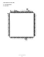
• 100-pin PQFP
• Supports PnP auto detect mode
• Compliant to Ethernet II and IEEE802.3 10Base5, 10Base2,
10BaseT
• Software compatible with NE2000 on both 8 and 16-bit slots
• Supports both jumper and jumperless modes
• Supports Microsofts Plug and Play configuration for jumperless mode
• Supports Full-Duplex Ethernet function to double channel bandwidth
• Supports three level power down modes:
– Sleep
– Power down with internal clock running
– Power down with internal clock halted
• Built-in data prefetch function to improve performance
• Supports UTP, AUI & BNC auto-detect
• Supports auto polarity correction for 10BaseT
• Supports 8 IRQ lines
• Supports 16 I/O base address options
--- and extra I/O address fully decode mode
• Supports 16K, 32K, 64K and 16K-page mode access to BROM (up to
256 pages with 16K bytes/page)
• Supports BROM disable command to release memory after remote
boot
• Supports flash memory read/write
• 16k byte SRAM built in
• Uses a 9346 (64*16-bit EEPROM) to store resource configurations
and ID parameters
• Capable of programming blank 9346 on board for manufacturing con-
venience
• Support 4 diagnostic LED pins with programmable outputs
2)-2. General Description
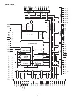
The RTL8019AS is a highly integrated Ethernet Controller which offers
a simple solution to implement a Plug and Play NE2000 compatible
adapter with full-duplex and power down features.
With the three level power down control features, the RTL8019AS is
made to be an ideal choice of the network device for a GREEN PC sys-
tem. The full-duplex function enables simultaneously transmission and
reception on the twisted-pair link to a full-duplex Ethernet switching hub.
This feature not only increases the channel bandwidth from 10 to 20
Mbps but also avoids the performance degrading problem due to the
channel contention characteristics of the Ethernet CSMA/CD protocol.
The RTL8019AS provides the auto-detect capability between the inte-
grated 10BaseT transceiver, BNC and AUI interface. Besides, the
10BaseT transceiver can automatically correct the polarity error on its
receiving pair.
The RTL8019AS is built in with a 16K-byte SRAM in a single chip. It is
designed not only to provide more friendly functions but also to save the
effort of SRAM sourcing and inventory.
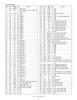
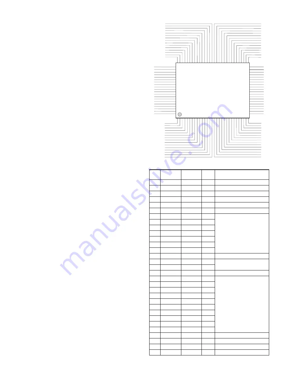
2)-3. Pin Configuration
LAN Controller
No.
CPU
Signal
name
I/O
Remarks
1
INT3
INT3
O
N.U. (Pull-Down)
2
INT2
INT2
O
N.U. (Pull-Down)
3
INT1
INT1
O
N.U. (Pull-Down)
4
INT0
/INTLAN
O
Interrupt to CPU
5
SA0
LA0
I
Address Bus
6
VDD
+5V
7
SA1
LA1
I
Address Bus
8
SA2
LA2
I
9
SA3
LA3
I
10
SA4
LA4
I
11
SA5
LA5
I
12
SA6
LA6
I
13
SA7
LA7
I
14
GND
GND
15
SA8
LA8
I
Address Bus
16
SA9
LA9
I
17
VDD
+5V
18
SA10
LA10
I
Address Bus
19
SA11
LA11
I
20
SA12
LA12
I
21
SA13
LA13
I
22
SA14
LA14
I
23
SA15
LA15
I
24
SA16
LA16
I
25
SA17
LA17
I
26
SA18
LA18
I
27
SA19
LA19
I
28
GND
GND
29
IORB
/MRD
I
Memory Read
30
IOWB
/MWE
I
Memory Write
31
SMEMRB
SMEMRB
I
N.U. (Pull-Up)
81 BD3 [IOS0]
82 BD2 [IOS1]
83 GND
84 BD1 [IOS2]
85 BD0 [IOS3]
86 GND
87 SD15
89 VDD
90 SD13
91 SD12
92 SD11
93 SD10
94 SD9
95 SD8
96 IOCS16B [SLOT16]
97 INT7 [IRQ15]
98 INT6 [IRQ12]
99 INT5 [IRQ11]
100 INT4 [IRQ10]
88 SD14
2 INT2 [IRQ4]
3 INT1 [IRQ3]
4 INT0 [IRQ2/9]
5 SA0
6 VDD
7 SA1
8 SA2
9 SA3
10 SA4
11 SA5
12 SA6
13 SA7
14 GND
15 SA8
29 IORB
28 GND
27 SA19
26 SA18
25 SA17
24 SA16
23 SA15
22 SA14
21 SA13
20 SA12
30 IOWB
19 SA11
18 SA10
17 VDD
16 SA9
64 AUI
63 LED2 [LED_TX]
62 LED1 [LED_RX] [LED_CRS]
61 LED0 [LED_COL] [LED_LINK]
60 LEDBNC
59 TPIN+
58 TPIN-
57 VDD
56 RX+
55 RX-
54 CD+
53 CD-
52 GND
51 X2
69 BA18 [BS2]
70 VDD
71 BA17 [BS3]
72 BA16 [BS4]
73 BA15
74 BA14 [PL0]
75 BCSB
76 EECS
77 BD7 [PL1][EEDO]
78 BD6 [IRQS0][EEDI]
79 BD5 [IRQS1][EESK]
80 BD4 [IRQS2]
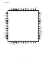
RTL8019AS
1 INT3 [IRQ5]
68 BA19 [BS1]
67 BA20 [BS0]
66 BA21 [PNP]
50 X1
49 TX+
48 TX-
47 VDD
46 TPOUT-
45 TPOUT+
44 GND
43 SD7
42 SD6
39 SD3
38 SD2
37 SD1
36 SD0
34 AEN
33 RSTDRV
32 SMEMWB
31 SMEMRB
41 SD5
40 SD4
35 IOCHRDY
65 JP
Summary of Contents for UP-3301
Page 91: ...UP 3301US PWB LAYOUT 89 CHAPTER 9 PWB LAYOUT 1 MAIN PWB A side ...
Page 92: ...UP 3301US PWB LAYOUT 90 B side 8 CUSTOMER DISPLAY PWB ...
Page 93: ...UP 3301US PWB LAYOUT 91 2 IR PWB 3 LCD PWB A Side B Side 4 INVERTER PWB A Side B Side ...
Page 94: ...UP 3301US PWB LAYOUT 92 5 MOTHER PWB 6 N F PWB 7 TOUCH PANEL PWB ...
Page 95: ...UP 3301US PWB LAYOUT 93 ...
Page 111: ......

