background image

MX-M503N  Dehumidifying heater  27 – 6

6)

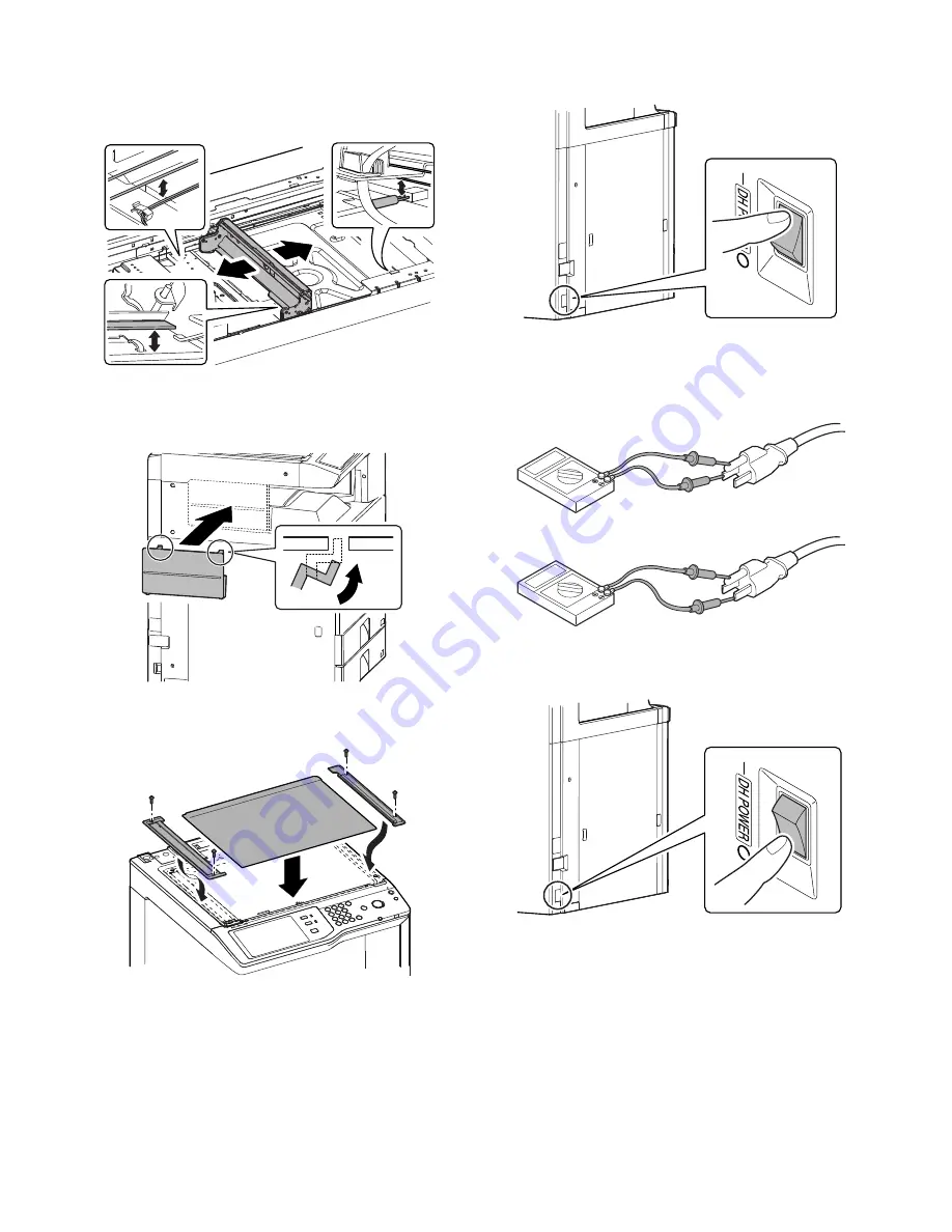
Move the lamp unit by hand and check that it move smoothly in
all movable area.

NOTE: Check that there is no interference of the harness of the

scanner heater in the wire and the 2/3 mirror unit.

(4) Installation of the table glass, the paper exit cover

1)

Install the paper exit cover.

2)

Install the table glass. Install the SPF glass and the glass
holder, and secure it with the screw.

F. Operation check after installation

1)

Turn on the dehumidifier heater switch.

2)

Measure the resistance value between the earth terminal and
the AC terminal (L side), and between the earth terminal and
AC terminal (N side) with the circuit tester, and confirm they
are not short-circuited.

3)

When not using the heater after checking, turn off the dehu-
midifier heater switch.

Summary of Contents for MX-M282N

Page 1: ... M282N M362N MX M452N M502N 1 CONFIGURATION 1 MX M283N M363N M363U M453N M453U M503N M503U M282N M362N M452N M502N 1 1 2 MX DEX8 DEX9 2 1 3 MX LCX1 3 1 4 MX FNX9 4 1 5 MX PNX1 5 1 6 MX RBX3 6 1 7 MX FN10 7 1 8 MX PNX5A B C D 8 1 9 MX FN11 9 1 10 MX PNX6A B C D 10 1 11 MX TRX2 11 1 12 MX FXX2 12 1 13 AR SU1 13 1 14 MX PB10 14 1 15 MX PB11 15 1 16 MX FWX1 16 1 17 MX EBX3 17 1 18 MX PKX1 18 1 19 MX P...

Page 2: ...stallation 11 1 12 MX FXX2 1 Unpacking 12 1 2 Installation 12 1 13 AR SU1 1 Unpacking 13 1 2 Installation 13 1 14 MX PB10 1 Unpacking 14 1 2 Installation 14 1 15 MX PB11 1 Unpacking 15 1 2 Installation 15 1 16 MX FWX1 1 Unpacking 16 1 2 Installation 16 1 17 MX EBX3 1 Unpacking 17 1 2 Installation 17 2 18 MX PKX1 1 Unpacking 18 1 2 Installation 18 1 19 MX PUX1 1 Unpacking 19 1 2 Installation 19 1 2...

Page 3: ...10 9 PAPER PASS UNIT MX RBX3 8 PAPER PASS UNIT MX RBX3 8 EXIT TRAY UNIT MX TRX2 6 STAND 1 x 500 SHEET PAPER DRAWER MX DEX8 3 STAPLE CARTRIDGE AR SC2 16 PUNCH MODULE MX PNX6 A B C D 15 FINISHER MX FN11 14 DIGITAL MULTIFUNCTIONAL SYSTEM MX M363U M453U M503U DIGITAL MULTIFUNCTIONAL SYSTEM MX M283N M363N M453N M503N DIGITAL MULTIFUNCTIONAL SYSTEM MX M282N M362N M452N M502N LARGE CAPACITY TRAY MX LCX1 ...

Page 4: ... finisher 8 PAPER PASS UNIT MX RBX3 9 SADDLE STITCH FINISHER MX FN10 10 PUNCH MODULE MX PNX1A B C D For inner finisher Printer expansion Memory Authentication Security Application Solution Image send expansion EXPANSION MEMORY BOARD MX SMX3 42 PRINTER EXPANSION KIT WITHOUT HDD For U model only MX PB10 17 PS3 EXPANSION KIT MX PKX1 19 PRINTER EXPANSION KIT WITH HDD For U model only MX PB11 18 STAMP ...

Page 5: ...COMPRESSION KIT MX EBX3 27 APPLICATION INTEGRATION MODULE MX AMX1 4 28 NETWORK SCANNER EXPANSION KIT MX NSX1 STD STD Authentication Security 29 DATA SECURITY KIT For the machine with HDD installed MX FR14U 4 Commercial version 30 DATA SECURITY KIT For the machine with HDD installed MX FR14 4 Authentication version 31 DATA SECURITY KIT For the machine without HDD installed MX FR15U Commercial versi...

Page 6: ...mpedance An electrical work is required Use of a step up transformer is also available In this case the capacity must be great enough for the max power consumption of the machine 3 Power frequency waveform The frequency must be within the range of the specified frequency 2 If power waveform is deformed a trouble may occur 4 Safety Be sure to properly ground the machine Grounding earth connection m...

Page 7: ...ected and a trouble may be caused 5 Vibration Avoid installation near a machine which produces vibrations If vibrations are applied to the copier machine copy images may be deflected and a trouble may be caused F Note for handling PWB and electronic parts When handling the PWB and the electronic parts be sure to observe the following precautions in order to prevent against dam age by static electr...

Page 8: ... Fusing unit 1 Be careful not to put fingerprints oil grease or other foreign material on the fusing roller and the external heating belt 2 Do not leave the fusing roller in contact state for a long time 2 Transit and delivery A Implements facility and manpower It is recommendable to use a forklift for bringing in the machine for safety If no forklift is available man power of two persons is requi...

Page 9: ... MX DEX8 or MX DEX9 then unpack the main unit and securely place the main unit on the MX DEX8 or MX DEX9 before installing the main unit A Lock release 1 Tray rotation plate lock release 1 Pull out the tray and remove the rotation plate fixing material and the tray note label 2 Attach the removed fixing material to the position shown in the figure for storage 2 Scanner 2 3 mirror unit lock release...

Page 10: ...prints or oil dirt on the roller surface Do not hold the case adjacent to the DV roller strongly 1 Open the front cabinet and remove the waste toner box 2 Remove the fixing screw of the developing unit and pull out the developing unit 3 Remove two screws Remove the DV cover 4 While supplying developer from the developer supply port of the developing unit turn the MC gear counterclockwise by using ...

Page 11: ... is not reflected When EXECUTE key is pressed during rotation the opera tion is stopped and EXECUTE key returns to the normal dis play If EE EU or EE EL is displayed setting of the reference toner density control value is not completed normally NOTE When not replacing the developer do not execute SIM25 2 Only execute SIM 25 2 when replacing the Developer SIM 25 2 should only be run immediately aft...

Page 12: ...ings key to configure the settings These settings specify the paper type paper size and func tions allowed for each paper tray When the Tray Settings key is touched a list appears showing the trays and the current settings 4 Touch the Change key in the above screen to change the set tings The following settings can be configured 2 Tray size setup 1 Pull out the paper tray Gently pull the tray out ...

Page 13: ...ing proce dures are not required SIM64 5 does not operate Note Before checking the printer density and gradation be sure to exe cute the following jobs Execute the high density image correction Process correction forcibly SIM 44 6 Execute the half tone image correction forcibly SIM 44 26 Method 1 Execute SIM 64 5 to print the print test pattern Set each set value to the default and press EXECUTE k...

Page 14: ...y digit 3 Press SET key and the password is set N USB PORT selection There are two USB ports one on the front frame side and the other on the rear frame side Only one of them can be used at a time Do not connect the two USB ports simultaneously When shipping the port on the front frame side is valid and the port on the rear frame side is invalid When using the USB port be care ful of the total cur...

Page 15: ...and packing parts C Check the packed items 1 Check that all the items are included in the package 2 Installation Note before installation Before starting installation check to insure that the data lamp on the operation panel does not light up or blink A Turn off the power of the main unit 1 Turn OFF the power switch on the operation panel 2 Open the front cabinet Turn OFF the power switch in the f...

Page 16: ... covers of the both sides of the main unit 2 Put the main unit on the desk unit Use man power of four persons or more to lift the main unit Place the main unit on the desk unit slowly by fitting the external lines Check to insure that the positioning pin on the top of the desk unit is securely engaged in the positioning groove of the main unit 3 Remove the No 2 paper feed tray 4 Pull out the No 3 ...

Page 17: ...t and left of the main unit front side and fix them with the fixing screws package part No 2 6 Replace the No 3 and No 2 trays to the original positions 7 Lift the connection plates and fix them with the fixing screws 8 Install the connection plate covers 1 2 2 1 2 1 ...

Page 18: ...was pulled out E Connector connection 1 Remove the screw from the back of the main unit Remove the connector cover 2 Connect the connector 3 Split the removed connector cover along the perforated line 4 Install the connector cover and fix it with a screw NOTE Before turning on the power check to insure that the fixing material of the tray is disengaged If the power is turned on without disengaging...

Page 19: ... off center adjustment When ALL is selected both of the above two items are executed simultaneously 4 Select a paper feed tray to be adjusted 5 Press EXECUTE key The patch image adjustment pattern is printed out 6 Set the adjustment pattern on the document table Any direc tion NOTE Fit the adjustment pattern correctly with the document guide 7 Press EXECUTE key The following item is automatically ...

Page 20: ...fore starting installation check to insure that the data lamp on the operation panel does not light up or blink A Turn off the power of the main unit 1 Turn OFF the power switch on the operation panel No Names of bundles Quantity 1 Mounting plate upper 2 2 Connection unit 1 3 Fixing screw A Hexagon with seat S tight M4 x 35 4 4 Fixing screw B Hexagon with seat S tight M4 x 12 2 5 Fixing screw C sc...

Page 21: ...l the mounting plate upper package part No 1 to the right side of the main unit with the fixing screw A package part No 3 When installing put the rubber section of the mounting plate upper on the lower side 2 Remove the right door cover from the machine 3 Disengage the pawl and remove the right adjuster 4 Remove the screw cap and remove the screw 5 Remove the cover 6 Temporarily fix the fixing scr...

Page 22: ...t closer to the main unit 2 Check to insure that the height adjustment check rib of the large capacity tray unit and the axis line of the mounting plate upper mounted to the main unit are in the same line 3 If the height adjustment is not required insert the large capac ity tray unit further more If the height adjustment is required perform the adjustment procedures from 4 4 Loosen the adjustment ...

Page 23: ... line of the mounting plate upper and insert the large capacity tray unit 7 Tighten the loosened screw D Connector connection 1 Remove the screw and remove the connector cover 2 Connect the connector and tighten the screw E Paper size switch 1 Paper size switch from A4 to LT Since the factory setting of the paper size is A4 if paper size switch is required perform the following procedures 1 Slowly...

Page 24: ...uide 3 Set the mark position of the auxiliary guide and the cas sette R to the size from A4 to LT and fix with the fixing screw flat screw At that time set the mark position of the auxiliary guide and the cassette R to the same scale of the mark position of the side plate R and the size guide adjustment plate con firmed in procedure 1 If the scale of the size guide adjust ment plate is at the cent...

Page 25: ...owing procedures 1 Slowly pull out the tray until it stops 2 Loosen the stopper fixing screw 1 pc on the right lower side of the tray so that the stopper does not function 3 Pull out the tray again until it stops a Side plate size switch 1 Remove four fixing screws blue screws which are fixing the upper and the lower sections of the side plate F and the side plate R 2 Adjust the mark position of t...

Page 26: ...ow Fix the upper section with the fixing screw blue screw which was removed previously NOTE When the rear edge shaft is switched to B5 check to confirm that the side plates F R are already set to B5 If the side plates F R are not set to B5 the rear edge shaft cannot be switched to B5 3 Slightly push the tray restore the stopper to the original posi tion and fix the fixing screw At that time check ...

Page 27: ...ter adjustment When ALL is selected both of the above two items are executed simultaneously 4 Select a paper feed tray to be adjusted 5 Press EXECUTE key The adjustment pattern is printed out 6 Set the adjustment pattern on the document table Any direc tion NOTE Fit the adjustment pattern correctly with the document guide 7 Press EXECUTE key The following item is automatically adjustment Print ima...

Page 28: ...large capacity tray 2 Slowly insert the tray to the original position Then make a copy to check to insure that there is no more shift Repeat the procedures until there is no shift b When the shift is in the rear side To adjust the print line in the direction B from the paper center as shown in the figure 1 Loosen two fixing screws red screws of the front rear size guide adjustment plate and move t...

Page 29: ...The punch position labels No 13 and No 14 should be kept at hand since they will be necessary when installing the punch unit No Packed part names Quantity 1 Finisher fixing plate 1 2 Front slide rail 1 3 Dummy punch unit 1 4 Front open close cover 1 5 Punch cover 1 6 Left front cover 1 7 Finisher slide stopper 1 8 Fixing screw 8 9 Resin clip 1 10 Coin screw 1 11 Staple position label For scanner 1...

Page 30: ...om the power out let B Removal of the paper holding plate unit 1 Disengage the pawl and remove the paper holding plate and the paper holding plate holder together as a unit Be careful to remove both of the paper holding plate which is easily removed alone and the paper holding plate holder C Installation of the inner finisher 1 Open the front cover 2 Remove two screws and remove the front cabinet ...

Page 31: ...three fixing screws package part No 8 and install the left front cover B package part No 6 with one fixing screw package part No 8 9 Fix the dummy punch unit package part No 3 with the fixing screw package part No 8 10 Check to insure that the slide roller is in the rail groove and insert the inner finisher 11 Fix the rear slide rail with the fixing screw package part No 8 12 After pushing the int...

Page 32: ...unch cover package part No 5 together with the band metal fixture with the fixing screw package part No 8 15 Install the front cabinet upper with two screws D Connector Installation 1 Remove the protection material and fixing tape 2 Remove the screw and remove the connector cover 3 Connect the finisher connector with the main unit connector and tighten with a screw 1 2 1 2 1 2 ...

Page 33: ...F Turn on the power of the main unit 1 Insert the power plug of the main unit into the power outlet 2 Open the front cabinet Turn ON the power switch in the front cabinet of the main unit 3 Turn ON the power switch on the operation panel Second label Corner R end fitting Label attachment reference Corner of the upper cabinet rear Corner R end fitting 1mm 1mm 1mm 1mm DSPF RSPF ON ...

Page 34: ...Note before installation Before starting installation check to insure that the data lamp on the operation panel does not light up or blink Do not install the punch unit first because doing so would cause interference between the inner finisher slide rail and the punch unit drawer connector possibly resulting in failure when you attempt to install the inner finisher A Turn off the power of the main...

Page 35: ...er slide stopper 4 Slide the inner finisher further more 5 Remove two screws and remove the front cabinet upper 6 Remove the screw and remove the band and the punch cover 7 Remove the screw and remove the dummy punch unit 8 Fix the punch unit with a screw When installing the punch unit be careful not to bump it against the drawer connector Fit the positioning pin and insert it 2 1 1 2 3 ...

Page 36: ...1 Remove the dust box 12 Fix the punch cover and the band together with one screw 13 Insert the dust box 14 Install the front cabinet upper part using the two screws removed in step 5 15 Insert the finisher slide stopper between the slide rail and the accuride and fix it with the coin screw 16 Slide the inner finisher to the original position and close the front cover A A 1 2 2 1 ...

Page 37: ... FNX9 D Turn on the power of the main unit 1 Insert the power plug of the main unit into the power outlet 2 Open the front cabinet Turn ON the power switch in the front cabinet of the main unit 3 Turn ON the power switch on the operation panel Second label Corner R end fitting Lose the clearance First label Label attachment reference Corner of the upper cabinet rear Corner R end fitting 1mm 1mm 1m...

Page 38: ...re that the data lamp on the operation panel does not light up or blink A Turn off the power of the main unit 1 Turn OFF the power switch on the operation panel 2 Open the front cabinet Turn OFF the power switch in the front cabinet of the main unit 3 Disconnect the power plug of the main unit from the power out let No Packed part names Quantity 1 Right cover plate 1 2 Interface left cabinet 1 3 R...

Page 39: ...remove the paper exit tray cover 3 Remove the screws and remove the paper exit tray When removing the paper exit tray there is no need to remove the screws in the section A 4 Remove the paper exit full detection actuator A and install the reverse detection actuator B package part No 6 Be careful of the installing direction of the reverse detection actuator 5 Engage the projection of the main unit ...

Page 40: ...surface of the right cover plate When inserting the reverse tray check to insure that the switch guide of the reverse tray is up 8 Fix the reverse tray with the resin clip package part No 5 9 Remove the front connection cabinet from the front cabinet upper and attach it to the front cabinet upper C package part No 7 10 Install the front cabinet upper C unit and fix with the screws 11 Insert the in...

Page 41: ... material and remove the top case Remove the packing cushion and bundled items 2 Holding the upper part of the saddle stitch finisher by two peo ple pull up the saddle stitch finisher and make it stand upright Be careful to sliding worker s foot 3 Remove the skid and packing cushions 4 One person tilt the saddle stitch finisher another person remove the lower tray 5 Remove the other side similarly...

Page 42: ...d on the front side of the option desk is securely installed Make sure that the connection plate package part No 2 included in the package is securely installed A Replacement of the Operation Manual storage cover 1 Remove the Operation Manual storage cover on the left side of the machine 2 Install the Operation Manual storage cover which was removed from the machine to the saddle finisher B Instal...

Page 43: ...e connection hole in the finisher 1 Loosen the fixing screw of the adjustment section on the rear side Adjust the height adjustment screw so that the guide pin is fit with the connection hole in the finisher By making space between the main body and ground the adjustment screw can be turned by the finger 2 Remove the two screws and remove the front under cover and foot cover 3 Loosen the fixing sc...

Page 44: ...height adjustment screws on the front rear sides to adjust so that the clearances are even By making space between the main body and ground the adjustment screw can be turned by the finger 4 When the clearances are even tighten the fixing screw of the adjustment section and install the foot cover E Connection of the main unit and saddle finisher 1 Fix the connection plate package part No 2 to the ...

Page 45: ...package part No 10 For DSPF RSPF package part No 11 H Turn on the power of the main unit 1 Insert the power plug of the main unit into the power outlet 2 Open the front cabinet Turn ON the power switch in the front cabinet of the main unit 3 Turn ON the power switch on the operation panel Label attachment reference Corner of the upper cabinet rear Corner R end fitting Corner R end fitting 1mm 1mm ...

Page 46: ... does not light up or blink A Turn off the power of the main unit 1 Turn OFF the power switch on the operation panel 2 Open the front cabinet Turn OFF the power switch in the front cabinet of the main unit 3 Disconnect the power plug of the main unit from the power out let 4 Disconnect the connector between the main unit and the sad dle finisher B Installation of the punch unit 1 Release the lock ...

Page 47: ...punch guide 6 Install the punch unit to the saddle finisher Fix the punch unit with the screw which was removed from the dummy punch guide Before installing remove the dust box Check to confirm that the punch guide pin is securely inserted into the guide pin insertion hole of the finisher Check to confirm that the pawl A is engaged with the plate frame 7 Connect the harness on the punch unit side ...

Page 48: ...processing label attachment 1 Open the front cover apply the punch jam processing label package part No 3 in position as shown in the figure D Punch position label attachment 1 Attach the label to the position indicated in the figure For scanner 1 2 000 0000 Label attachment reference Second label Corner R end fitting Lose the clearance First label Label attachment reference Corner of the upper ca...

Page 49: ...the main unit 1 Connect the connector 2 Insert the power plug of the main unit into the power outlet 3 Open the front cabinet Turn ON the power switch in the front cabinet of the main unit 4 Turn ON the power switch on the operation panel 1mm 1mm 1mm 1mm DSPF RSPF ON ...

Page 50: ...aterial and remove the top case 2 Remove the bundled items from packing cushion 3 Holding the upper part of the saddle stitch finisher by two peo ple pull up the saddle stitch finisher and make it stand upright Be careful to sliding worker s foot 4 Remove the skid and packing cushions 5 One person tilt the finisher another person remove the lower tray 6 Remove the other side similarly ...

Page 51: ...11 and No 12 should be kept at hand since they will be necessary when installing the punch unit No Names of bundles Quantity 1 Binding head round tapping M4x8 2 2 IT tapping M4x20 2 3 Binding head M4x12 4 4 Step screw B 2 5 Rail 1 6 Rail reception sheet metal 1 7 Connection fixture F for x3 1 8 Connection fixture R for x3 1 9 Staple position label For scanner 1 10 Staple position label For RSPF DS...

Page 52: ...l storage cover 1 Remove the Operation Manual storage cover on the left side of the machine 2 Install the Operation Manual storage cover which was removed from the machine to the finisher B Installation of the rail 1 Install the rail Package part No 5 to the finisher with the fix ing screws Package part No 1 2 Install the rail reception sheet metal Package part No 6 to the main unit with the fixin...

Page 53: ...g the mylar 1 Attach the mylar package part No 13 to the position indicated in the figure E Installation of the connection fixture F R 1 Install the connection fixture R Package part No 8 to the main unit with the fixing screws Package part No 3 2 Install the connection fixture F Package part No 7 to the main unit with the fixing screws Package part No 3 Corner reference Corner reference Reference...

Page 54: ...ew and remove the connector cover on rear side of the finisher 3 Check that the center of the screw hole of the finisher is in the range of specification of an oval hole of the connection fixture that exist on main body rear side When not the range of specification progress to the proce dure of H Adjustment If the adjustment is not required remove the screws from the screw hole directly and push t...

Page 55: ...er cover and remove it 3 Open the front upper door and remove the screw 4 Remove the screws and open the front cover 5 Remove the fixing tapes 6 Remove the screws and remove the auxiliary wheels 7 Remove the screws and remove the rear lower cover 8 Remove the fixing tapes ...

Page 56: ...10 Remove the screw and remove the spanner installed inside the front lower door 11 Turn the bolt for which the adjustment is necessary and adjust to become it within the range of specification 12 Check to insure that the upper and lower clearances between the main unit and the finisher are even ...

Page 57: ... Install the rear lower cover with the fixing screws 15 Install the auxiliary wheels with the fixing screws 16 Install the spanner for adjustment to inside the front lower door 17 Close the front cover and secure it with the fixing screws 18 Attach the fixing screw and close the front upper door ...

Page 58: ...the main unit 2 Open the front cover of finisher 3 Fix the finisher to the main unit with the step screw B Package part No 4 4 Close the front cover 5 Remove the screw and remove the connector cover on rear side of the finisher 6 Install the Step screw B Package part No 4 7 Attach the connector cover on rear side of the finisher ...

Page 59: ...or scanner Package part No 9 For DSPF RSPF Package part No 10 L Turn ON the main power switch of the main unit 1 Connect the power plug of the main unit into the power outlet 2 Open the front cabinet of the main unit Turn ON the power switch in the front cabinet 3 Turn ON the power switch on the operation panel Label attachment reference Corner of the upper cabinet rear Corner R end fitting Corner...

Page 60: ...t of the punch unit 1 Pull out the punch unit B Removal of the protection material 1 Remove the fixing tape and protection material 2 Open the front cover and open the top cover 3 Remove the screws and remove the fixing material 2 posi tions 4 Close the top cover and close the front cover 1 2 1 2 ...

Page 61: ... step screws installed to the fin isher 4 Tighten the step screws bundled to the punch unit fix the punch unit 5 Attach the front cover mounting fixture Package part No 6 with the fixing screws Package part No 3 Remove the screw of the finisher and reuse it Install it using the reuse screw and three fixing screws Package part No 3 bundled to punch unit No Names of bundles Quantity 1 P tight M4x12 ...

Page 62: ...WB of punch unit and fix the harness to the clamp C Install of the Connection fixture F R 1 Install the Connection fixture F Package part No 7 to the main unit with the fixing screws Package part No 4 2 Install the Connection fixture R Package part No 8 to the main unit with the fixing screws Package part No 4 D Check of the connected position of main unit and finisher 1 Engage the finisher that h...

Page 63: ...o the proce dure of E Adjustment If the adjustment is not required remove the screw from the screw hole directly and push the caster into it until the instal lation fixing E Adjustment Refer to the adjustment procedures in the MX FN11 Service Manual F Install to main unit 1 Engage the finisher that has installed punch unit to the main unit 2 Open the front door of punch unit 3 Secure the main unit...

Page 64: ...stall the connector cover of the finisher and fix it with the fix ing screw G Connection of connector to the main unit 1 Connect two connectors of the finisher to the main unit and tighten the screws H Punch position label attachment 1 Attach the punch position label to the position indicated in the figure For scanner Package part No 11 of the MX FN11 Second label Corner R end fitting Lose the cle...

Page 65: ...I Turn ON the main power switch of the main unit 1 Connect the power plug of the main unit into the power outlet 2 Open the front cabinet of the main unit Turn ON the power switch in the front cabinet 3 Turn ON the power switch on the operation panel 1mm 1mm 1mm 1mm DSPF RSPF ON ...

Page 66: ...he power of the main unit 1 Turn OFF the power switch on the operation panel 2 Open the front cabinet Turn OFF the power switch in the front cabinet of the main unit 3 Remove the power plug of the main unit from the outlet B Installation of the exit roller unit 1 Open the right door 2 Remove the screw and remove the connector cover 3 Remove the screw Disengage the engagement in the front side then...

Page 67: ... tray unit A and the full detection actuator B package part No 2 Be careful of the installing direction of the full detection actu ator C Turn on the power of the main unit 1 Insert the power plug of the main unit into the power outlet 2 Open the front cabinet Turn ON the power switch in the front cabinet of the main unit 3 Turn ON the power switch on the operation panel D Tray setting Use SIM26 1...

Page 68: ... tion 3 Remove the power plug of the main unit from the outlet B Attach the fax box unit to the rear part of the main unit 1 Remove the two screws from the rear cabinet of the main unit 2 Attach the supplied step screw to one of the two positions from which the screws are removed 3 Insert the step screw into the mounting hole of the fax box unit 4 Use a screw that has been removed in step 1 to sec...

Page 69: ...h the bundled M3 screw F Attach the control PWB and the right cabinet rear 1 Push the control PWB unit into the main unit and secure it with the two screws 2 Cut out the cut out portion of the right cabinet rear 3 Fit the interface cable into the opening that has been cut 4 Attach the right cabinet rear cover to the main unit At this time check that the four hooks are properly fitted to the main u...

Page 70: ...ations CHINA China ON ǂǂǂ6 08 7 21ǂǂ12 26 7 67 67 1 7 21 6 783 87 8 6 1 3 1 1 B 8523 86 8 B 1 Country code list JAPAN 00000000 SWITZERLAND 10100110 U S A 10110101 AUSTRIA 00001010 AUSTRALIA 00001001 INDONESIA 01010100 U K 10110100 THAILAND 10101001 FRANCE 00111101 MALAYSIA 01101100 GERMANY 00000100 INDIA 01010011 SWEDEN 10100101 PHILIPPINES 10001001 NEWZEALAND 01111110 HONGKONG 01010000 CHINA 0010...

Page 71: ...lephone wind the line cable around the supplied ferrite core by two turns and connect the cable to the modular jack indicated with TEL L Installation completion check 1 Execute SIM 22 10 to check to confirm that the FAX box and the FAX memory are properly installed When the FAX1 is properly connected MX FXX2 is dis played When the FAX memory is properly connected AR MM9 is displayed ǂǂǂ6 08 7 21ǂǂ...

Page 72: ...ata lamp on the installation panel does not light or flash A Turn off the power of the main unit 1 Turn OFF the power switch on the operation panel 2 Open the front cabinet and turn OFF the power switch 3 Disconnect the power plug from the power outlet B Install the stamp unit 1 Open the DSPF RSPF unit and remove the OC mat For removing and fixing screws use a stubby screwdriver If stubby screwdri...

Page 73: ... the install ing screw package part No 4 Fix it together with the earth wire 4 Install the stamp case unit and connect the connector 5 Install the sensor cover 6 Install the stamp cartridge package part No 3 7 Install the OC mat and close the DSPF RSPF unit If the angle adjustment plate was lowered for installation lift the angle adjustment plate and fix it with the screw and close the DSPF RSPF u...

Page 74: ...n unit 1 Insert the power plug into the power outlet 2 Open the front cabinet of the machine and turn ON the power switch 3 Turn ON the power switch on the operation panel 4 Use SIM22 10 to check to confirm that the finish stamp AR SU1 is recognized ON ...

Page 75: ...n key 2 After completion of entry of the product key turn OFF the power switch on the operation panel Turn OFF the main power switch then turn ON the power switch and the main power switch again 3 Use the attached CD ROM to install the driver For installing procedures refer to the software setup guide Installation of the driver must be performed by the user or the serviceman with assistance or the...

Page 76: ... with out HDD In that case however the user settings and the registered data are initialized 1 Use the device cloning function to backup the user setting data stored in the SRAM and the EEPROM to a PC or USB mem ory Use the device cloning function on either the system setting or the Web Page menu to backup the data 2 Use the storage backup function to backup the user data stored in the HDD to a PC...

Page 77: ...TE Be sure to perform this procedure in order to protect the memory and the Flash ROM on the MFP PWB If this procedure is neglected a stress may be applied to the memory and the Flash ROM on the MFP PWB causing a trouble 2 Install the HDD to the MFP PWB frame When installing the HDD to the MFP PWB frame attach the anti vibration rubber to the HDD frame side and fix it with a screw 3 Connect the HD...

Page 78: ... the driver must be performed by the user or the serviceman with assistance or the user NOTE If any trouble occurs during installing procedures cancel the trouble H User data restoring procedures The data saved in the PC in the preliminary arrangement are restored to the SRAM the EEPROM and the HDD When this option is installed to a machine which has been used by a user be sure to backup the user ...

Page 79: ...2 After completion of entry of the product key turn OFF the power switch on the operation panel Turn OFF the main power switch then turn ON the power switch and the main power switch again After completion of 1 and 2 the Internet Fax send function from the main unit becomes enable To enable the Internet Fax send with the PC FAX driver the following steps 3 and 4 are required 3 Use the CD ROM packe...

Page 80: ...for installation Firmware The firmware must be revised to the latest version The ACRE firmware version must be 02 00 J2 or later C Type B Type C 1 Parts included The MX EBX3 of type B is provided with all the parts necessary for installation Firmware Basically the firmware of the machine of type B may not revised For double sure however use SIM22 5 to check the firmware version and revise to the l...

Page 81: ...w from the right cabinet rear 3 Remove the right cabinet rear 4 Remove the two screws from the control PWB unit If the fax box unit is installed carry out steps 5 6 and 7 additionally 5 Pull out the control PWB unit and remove the snap band 6 Remove the interface cable from the frame 7 Remove the connector 8 Pull out and remove the control PWB unit C Installation of the scanner function expansion ...

Page 82: ...portion of the sheet metal on the control PWB unit 3 Attach the snap band to the sheet metal of the control PWB unit 4 Push the control PWB unit into the main unit 5 Secure the unit with the two screws 6 Fit the interface cable into the right cabinet rear cover 7 Attach the right cabinet rear cover to the main unit At this time check that the four hooks are properly fitted to the main unit 8 Secur...

Page 83: ...he firmware version of the MX EBX3 The ACRE version must be 02 00 J2 or later If the version is 01 00 J2 revise the version according to the procedure of 5 5 Use SIM49 1 to revise the firmware to the latest version Then perform the procedure of 4 ON ǂǂǂ6 08 7 21ǂǂ12 26 7 67 6 1 8 0 1 1 8 227 32 5 21 1 8 0 18 5 3 7 5 0 5 3 8 6 3 6 8 3 63 5 227 5 0 1 5 7 0 1 121 0 1 121 6 121 1 6 5 381 ...

Page 84: ...pass it to the user A Preparation for enabling PS3 1 To enable PS3 enter the product key by the key operation of the copier machine a Touch PRODUCT KEY INPUT b Touch the input column c Enter the product key with the 10 key and touch OK key 2 After completion of the product key entry turn OFF the power switch and the main power switch and turn them ON B PS3 check 1 Print the test page in PS3 fonts ...

Page 85: ... input column d Enter the product key with numeric key 10 key and touch Registration key 2 After completion of entry of the product key turn OFF the power switch on the operation panel Turn OFF the main power switch then turn ON the power switch and the main power switch again 3 Use the CD ROM packed together with the machine to install the XPS driver For installing procedures refer to the softwar...

Page 86: ...e filter cover from the right cabinet rear 2 Remove the screw from the right cabinet rear 3 Remove the right cabinet rear 4 Remove the two screws from the control PWB unit If the fax box unit is installed carry out steps 5 6 and 7 additionally 5 Pull out the control PWB unit and remove the snap band 6 Remove the interface cable from the frame 7 Remove the connector 8 Pull out and remove the contro...

Page 87: ...to the recessed portion of the sheet metal on the control PWB unit 3 Attach the snap band to the sheet metal of the control PWB unit 4 Push the control PWB unit into the main unit 5 Secure the unit with the two screws If the fax box unit is installed carry out step 6 addition ally 6 Fit the interface cable into the right cabinet rear cover 7 Attach the right cabinet rear cover to the main unit At ...

Page 88: ...MX M503N MX SMX3 20 3 2 Turn on the main power switch 3 Turn on the power switch located on the operation panel ON ...

Page 89: ...emove the ozone filter cover from the right cabinet rear 2 Remove the screw from the right cabinet rear 3 Remove the right cabinet rear 4 Remove the two screws from the control PWB unit If the fax box unit is installed carry out steps 5 6 and 7 additionally 5 Pull out the control PWB unit and remove the snap band 6 Remove the interface cable from the frame 7 Remove the connector 8 Pull out and rem...

Page 90: ...ain unit 1 Insert the power plug of the main unit to the outlet 2 Turn on the main power switch 3 Turn on the power switch located on the operation panel F PCL expansion font list check 1 PCL expansion font list check Select the PCL expansion font list by the procedures described in the printer test page in the system setup guide Check to confirm that the barcode font list is printed G Font list 1...

Page 91: ...it all the data to clear the data remaining in the main unit and then start installation Check to insure that neither the LINE indicator nor the DATA indicator on the operation panel does light up or blink A Turn off the power switches of the main unit 1 Turn the power switch located on the operation panel to the OFF position 2 After checking that the operation panel has gone out open the front ca...

Page 92: ...o the main unit 5 Secure the unit with the two screws If the fax box unit is installed carry out step 6 addition ally 6 Fit the interface cable into the right cabinet rear cover 7 Attach the right cabinet rear cover to the main unit At this time check that the four hooks are properly fitted to the main unit 8 Secure the right cabinet rear with the screw 9 Attach the ozone filter cover to the main ...

Page 93: ...1 Turn OFF the power switch on the operation panel 2 Open the front cabinet Turn OFF the power switch in the front cabinet of the main unit 3 Disconnect the power plug of the main unit from the power out let B Install the USB hub PWB 1 Remove the screw and remove the rear cabinet No Name of parts in the package Quantity 1 Keyboard unit 1 2 Operation base plate C 1 3 USB hub PWB unit 1 4 Mother PWB...

Page 94: ...ctor of the scan mother harness and con nect the mother PWB connection harness part No 4 in the package 5 Attach the rear cabinet and fix it with the screws C Install the base unit 1 Place the protection sheet part No 7 in the package on the table glass 2 Open the front cabinet and remove the screw and remove the front cabinet upper 3 Remove the screw and remove the operation base plate unit 1 2 ...

Page 95: ... the keyboard unit part No 1 in the package and fix it with the fixing screw A part No 5 in the package and the fixing screw B part No 6 in the package When fixing the fixing screw B use the short screwdriver or the small screwdriver D Install the operation panel 1 Check that each harness is engaged with the rib 2 Connect the connector 3 Install the operation panel to the main unit and fix it with...

Page 96: ...n the operation panel G Check the keyboard input 1 Touch IMAGE SEND on the touch panel 2 Touch SEND SETTING on the touch panel 3 Touch FILE NAME DIRECT ENTRY on the touch panel 4 Enter the keyboard input and check the input on the touch panel H Language setting Targets The model for 8 5 inch LCD panel with option keyboard installed The language selected should be the same as the layout of the opti...

Page 97: ...ng The layout of the keyboard that appears in the text entry screens can be changed English US English UK French German Swedish Norwegian Finnish Danish Russian Greek Turkish Image Quality Adjustment Back Clock Adjust Keyboard Select D De ef fa au ul lt t S Se et tt ti in ng gs s S Sy ys st te em m S Se et tt ti in ng gs s Keyboard Select C Cl lo oc ck k A Ad dj ju us st t S Sy ys st te em m S Se ...

Page 98: ...a Press the system setting key on the operation panel b Select page 2 2 of the system setting and touch Product key input key c Touch the input column d Enter the product key with numeric key 10 key and touch Registration key 2 After entering the product key information turn OFF the power switch and the main power switch of the machine and turn them ON again For the models with the main power swit...

Page 99: ...1 OSA setting key is added to the menu screen of the system setting or the key operator pro gram 2 When OSA setting key is touched the menu below is dis played 3 When the Default Display Setting key is touched the screen for setting the default display that appears when the DOCU MENT FILING key is pressed will appear To set the base screen of document filing as the default dis play touch the Docum...

Page 100: ...ow is dis played 3 When External Account Setting key is touched the screen for setting the calculation by the external application and for enabling user authentication is displayed The two settings are linked together When the check box of External Account Management is Enabled is checked The result of the job completion is notified to the external application set on the Web page The default is Di...

Page 101: ...1FCZZ 1 Dehumidifier heater switch QSW C9294QCZZ AF 1 2 Label for heater switch TLABZ5256FCZZ AH 1 3 Supporter LSUPP0118FCPZ AB 5 4 WH PWB CPWBF1675FC338 AQ 1 5 AC WH harness 1 DHAI 3755FCZZ AH 1 AC WH harness 2 DHAI 3756FCZZ AE 1 Not used in this model Heater kit DKIT 0385FCZZ 120V series DKIT 0386FCZZ 230V series 6 Heater 120V series RHETP0131FCPZ BE 1 Heater 230V series RHETP0132FCPZ 7 Heater m...

Page 102: ...C cable connection plate only for 120V series or remove the inlet mounting plate only for 230V series Remove the core This procedure only applies to the 230V series 2 Remove the snap band Insert the supporter package part No 3 to the frame of the power unit and attach the WH PWB package part No 4 on it NOTE Be careful not to break the PWB when mounting the PWB to the supporters 3 Connect the harne...

Page 103: ... into the T Heater cover 3 Attach the caution label package part No 10 to the T Heater cover NOTE Wipe the surface where the label is to be affixed with alco hol then attach the label along the reference line 2 Installation of the heater unit 1 Remove the tray 1 and the tray 2 2 Install the heater unit to the main unit and secure it with the screw M3x5 S tight package part No 11 Pass the harness o...

Page 104: ...binet and secure it with the screw E Installation of the scanner heater kit 1 Assembling of the scanner heater unit 1 Secure the marking position on the harness of the scanner heater package part No 13 to the heater fixing plate package part No 14 with the banding band package part No 15 2 Extend the harness and secure the other position of it with banding band packing part No 15 3 Tighten the sna...

Page 105: ... the scanner bottom 3 Connect the harness of the scanner heater Install the heater fixing plate of the scanner heater unit and secure it with the screw M3x4 Round tipped package part No 17 4 Install the scanner heater and secure it with the screw M4x6 Bind machine screw package part No 18 Pass the harness through the clamp NOTE The convex part of the scanner heater must be inserted into the hole o...

Page 106: ...stall the paper exit cover 2 Install the table glass Install the SPF glass and the glass holder and secure it with the screw F Operation check after installation 1 Turn on the dehumidifier heater switch 2 Measure the resistance value between the earth terminal and the AC terminal L side and between the earth terminal and AC terminal N side with the circuit tester and confirm they are not short cir...

Page 107: ...rn OFF the power switch on the operation panel 2 Open the front cabinet Turn OFF the power switch in the front cabinet of the main unit 3 Disconnect the power plug of the main unit from the power out let B RSPF unit installation 1 Remove the screws and remove the glass holder A Remove the table glass B Remove the screws and remove the glass holding left OC C Arrange the SPF glass unit D package pa...

Page 108: ...ose 4 Loosen the screw on the angle adjustment plate in the rear side of the machine and lower the angle adjustment plate 5 Raise the RSPF unit upright and fix it with the accessory screw M5 x 16 package part No 4 6 Remove the connector cover Connect the interface connector Check to insure that the projection A of the interface connec tor is in the groove on the main unit side as shown in the fig ...

Page 109: ...ht adjustment sheet between section A and the RSPF glass height adjustment resin surface a and close the RSPF unit b If it cannot be pulled out loosen the fixing nut and turn the section D clockwise to lift the RSPF unit and make an adjustment If it can be pulled out without resistance loosen the fixing nut and turn the section D counterclockwise to move down the RSPF unit and make an adjustment B...

Page 110: ...on F If not loosen the fixing nut and turn the section E to adjust Use a clearance gauge to check to confirm that the clearance in the section F is 4 3mm 5 0mm Turn section E clockwise to lift the RSPF unit Turn it counterclockwise to move down the RSPF unit Insert a clearance gauge in the range of 20mm from the edge a of the OC mat Adjust the section F E 20mm a Section F 4 3 5 0mm 1 10 Jun 18 1 ...

Page 111: ... Check to confirm that the projection in section C in the right front side of then RSPF bottom is in contact with the glass surface b d Check section B Check to insure that a slight resistance is felt when pulling out the RSPF height adjustment sheet If the boss in section B is in contact it is O K Slowly pull out the RSPF height adjustment sheet Place the RSPF height adjustment sheet between sect...

Page 112: ... adjustment chart created in step 1 to A3 11 x 17 paper in RSPF duplex mode and then check the image for skews Set in the RSPF feed tray so that the mark on the adjustment chart is at the edge Check with one of the following methods Check Method 1 Check Method 2 Check that the squareness of the main scanning direction print line for the longitudinal direction of paper is within 1 0mm If the above ...

Page 113: ...d The RSPF paper feed tray unit has been replaced When a U2 trouble occurs The scanner PWB has been replaced The EEPROM on the scanner PWB has been replaced 1 Enter the SIM 53 6 mode 2 Open the RSPF paper feed guide to the maximum width posi tion 3 Press EXECUTE key The maximum width detection level is recognized 4 Open the RSPF paper feed guide to the width for the A4R size 5 Press EXECUTE key Th...

Page 114: ...SPF original leading edge adjustment front side RSPF original off center adjustment front side RSPF sub scan magnification ratio adjustment front side 8 RSPF adjustment patterns are loaded into the RSPF By pressing the REPRINT button you can return to the cassette selection screen and have the machine self print RSPF adjustment patterns again 9 Press the EXECUTE button and the machine starts loadi...

Page 115: ...free solder is about 220 C which is about 40 C higher than that of conventional lead solder and its soldering capacity is inferior to conventional one it is apt to keep the soldering iron in contact with the PWB for longer time This may cause land separation or may exceed the heat resistive temperature of components Use enough care to separate the soldering iron from the PWB when completion of sol...

Page 116: ...sfara vid felaktigt batteribyte Använd samma batterityp eller en ekvivalent typ som rekommenderas av apparattillverkaren Kassera använt batteri enligt fabrikantens instruktion German Achtung Explosionsgefahr bei Verwendung inkorrekter Batterien Als Ersatzbatterien dürfen nur Batterien vom gleichen Typ oder vom Hersteller empfohlene Batterien verwendet werden Entsorgung der gebrauchten Batterien nu...

Page 117: ...Server 2008 and Internet Explorer are registered trademarks or trademarks of Microsoft Corporation in the U S A and other countries PostScript is a registered trademark of Adobe Systems Incorporated Macintosh Mac OS AppleTalk EtherTalk Laser Writer and Safari are registered trademarks or trademarks of Apple Computer Inc IBM PC AT and Power PC are trademarks of International Business Machines Corpo...

Reviews: