DX-SX1H
– 50 –
CTL1
CTL2
CH1
CH2
CH3
CH4
CH5
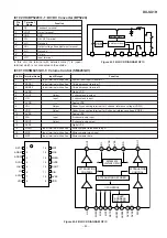
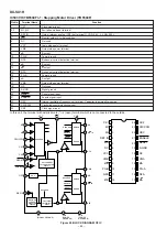
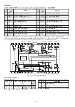
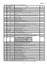
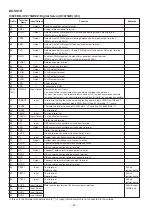
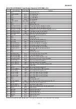
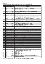
IC506 VHiBA6796FP-1: Loading/Focus/Tracking/Spin/Sled Driver (BA6796FP)
Note 1: Positive output/negative output means polarity toward input. (Ex. 18 pin output 'H' in case of 19 pin input 'H')
Note 2: Tray positive output/tray negative output means polarity toward mode. (Ex. 11 pin output 'H' in case of the forward mode)
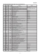
In this unit, the terminal with asterisk mark (*) is (open) terminal which is not connected to the outside.
Pin
No.
Terminal
Name
Function
Pin
No.
Terminal
Name
Function
1*
OPOUT
Operational amplifier output terminal
15
CH2-OUT-
CH2 negative output terminal
2
CH4-IN
CH4 input terminal
16
CH2-OUT+
CH2 positive output terminal
3*
CH4-IN'
CH4 gain adjustment input terminal
17
CH1-OUT-
CH1 negative output terminal
4
CTL1
Control 1 input terminal
18
CH1-OUT+
CH1 positive output terminal
5
CTL2
Control 2 input terminal
19
CH1-IN
CH1 input terminal
6
FWD
Tray forward input terminal
20
CH1-IN'
CH1 gain adjustment input terminal
7
REV
Tray reverse input terminal
21
VCC
VCC
8
TRAY-IN
Tray input terminal
22
CH2-IN
CH2 input terminal
9
GND
Substrate GND
23*
CH2-IN'
CH2 gain adjustment input terminal
10
CH5-OUT-
Tray negative output terminal
24*
CH3-IN
CH3 input terminal
11
COM-OUT
Tray positive terminal/CH4 negative output terminal
25*
CH3-IN'
CH3 gain adjustment input terminal
12*
CH4-OUT+
CH4 positive output terminal
26
VREF-IN
Bias amplifier input terminal
13*
CH3-OUT+
CH3 positive output terminal
27*
OPIN+
Operational amplifier non-inversion input terminal
14*
CH3-OUT-
CH3 negative output terminal
28*
OPIN-
Operational amplifier inversion input terminal
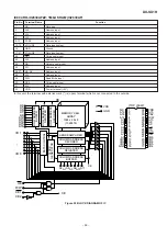
28
27
26
25
24
23
22
21
20
19
18
17
16
15
CH2-OUT
CH1-OUT
CH1-IN
CH2-IN
CH3-IN
10K
10K
13.3K
13.3K
13.3K
10K
+
-
VCC
D
D
D
D
D
D
D
D
D
V/I
T.S.D
26.6K
10K
CTL1
CTL2
PWD
REV
LOGIC
1
2
3
4
5
6
7
8
9
10
11
12
13
14
CH4-IN
CH5-IN
CH5-OUT CH4-OUT CH3-OUT
+
-
+
-
+
-
+
-
LEVEL SHIFT
LEVEL SHIFT
LEVEL SHIFT
LEVEL SHIFT
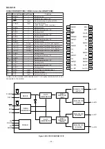
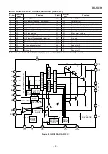
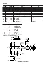
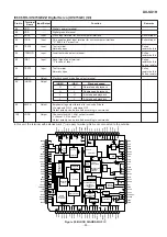
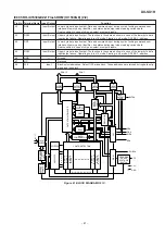
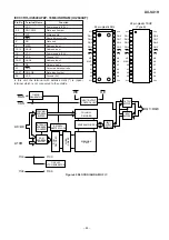
Figure 50 BLOCK DIAGRAM OF IC
Mode Switching Table
For CTL1 and CTL2
L
L
OFF
ON
L
H
H
L
ON
OFF
H
H
OFF
ON
OFF
ON
Note: Output: high impedance in case of OFF.
For F and R (CH5 control is effective only in case of ON)
F
R
Output Mode
L
L
High impedance
L
H
Reverse
H
L
Forward
H
H
Break

