DX-SX1H
– 49 –
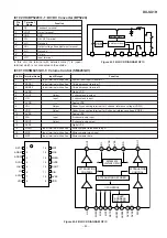
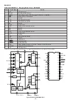
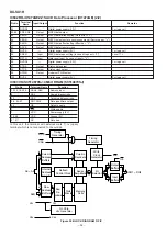
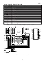
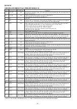
IC504 RH-iX2842AFZZ: Spindle Motor Driver (IX2842AF)
In this unit, the terminal with asterisk mark (*) is (open) terminal which is not connected to the outside.
Pin No.
Terminal
Name
Function
Pin No.
Terminal
Name
Function
1
PG
Power GND terminal
15
SG
Signal GND terminal
2
H1+
Hall element 1 positive input terminal
16
VCC
Power terminal
3
H1-
Hall element 1 negative input terminal
17
ECR
Torque instruction reference input terminal
4*
NC
Not used
18
EC
Torque instruction input terminal
5
H2+
Hall element 2 positive input terminal
19*
NC
Not used
6
H2-
Hall element 2 negative input terminal
20
PCI
Current feedback phase compensating terminal
7
VH
Hall bias terminal
21
VM
Motor power terminal
8
H3+
Hall element 3 positive input terminal
22
CS1
Current detection terminal 1
9
H3-
Hall element 3 negative input terminal
23*
NC
Not used
10
SS
Start/Stop switching terminal
24*
NC
Not used
11*
TFLG
Thermal protection monitor terminal
25*
NC
Not used
12
FG
FG signal output terminal
26
A3
Drive output 3
13
BRK
Break mode set terminal
27
A2
Drive output 2
14*
NC
Not used
28
A1
Drive output 1
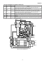
2
H1+
3
H1-
5
H2+
8
H3+
6
H2-
9
H3-
7
VH
18
EC
17
10
ECR
S/S
16
Vcc
20
PCI
13
BRK
11
TSDF
12
FG
1
PG
26
A3
27
A2
28
A1
22
CS1
21
VM
15
SG
ER
EA
VTL
EP=ER x EA
FG
COMPARATOR
+ -
MATRIX HALL AMPLIFIER
DETE-
CTION
DIRECTION
DETECTION
DIRECTION SWITCHING
UPPER-SIDE
DISTRIBUTION
AMPLIFICATION
AMPLIFICATION
LOWER-SIDE
DISTRIBUTION
HALL BIAS
LOGIC
ABSOLUTE
VALUE
START/
STOP
THERMAL
PROTECTION
CIRCUIT
BREAK
CIRCUIT
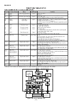
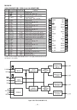
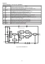
Figure 49 BLOCK DIAGRAM OF IC

