


AR-M550/M620/M700 INSTALLATION MANUAL (AR-LC6) 2 - 7
K. Carry out the print off center adjustment
(1) Adjustments with simulations
Since the off-center adjustment has been made at shipping, there is
normally no need to adjust. If, however, the center is shifted, carry out
the following steps to adjust.
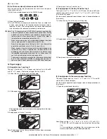
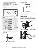
1) Set a test chart (document) on the document table properly.
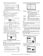
2) Execute SIM 50-5 (Print off center) by the key operation of the
main unit.
3) In SIM 50-5, the display is shown as follows to allow setting of the
print off center adjustment value for each paper feed tray.
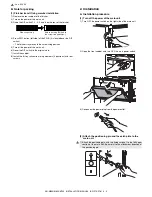
[When shifted to the front side]
When the print line is shifted from the center of paper in the direction A:
Increase the value.
Then make a copy to check that the center is not shifted.
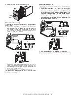
[When shifted to the rear side]
When the print line is shifted from the center of paper in the direction B:
Decrease the value.
Then make a copy again to check that the center is not shifted. Repeat
this procedure as required.
∗
For details of the adjustment and check procedures, refer to the
chapter of adjustments in the Service Manual of the main unit.
(2) Mechanical adjustment
Since the off-center adjustment has been made at shipping, there is
normally no need to adjust. If the center is shifted, however, adjust with
the simulation. If the shift is not recovered, perform the following steps
to adjust.
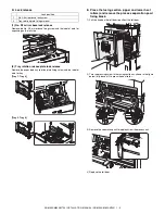
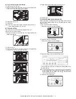
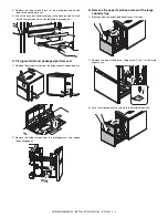
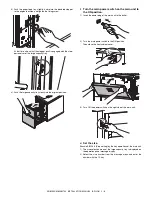
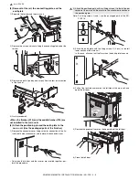
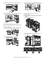
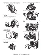
1) Pull out the large capacity tray until it stops.
2) Loosen the stopper fixing screw (1 pc.) on the lower right side of
the paper feed tray to disable the stopper function.
Adjustment position
Set value
Display
item
Item description
Default
Set
range
TRAY1 TRAY1
(LCC left
side)
Print off center
adjustment position
TRAY2 TRAY2
(LCC right
side)
Print off center
adjustment position
TRAY3 TRAY3
Print off center
adjustment position
TRAY4 TRAY4
Print off center
adjustment position
BPT
Manual
paper feed
Print off center
adjustment position
LCC
Large
capacity tray
Print off center
adjustment position
50
0 to
99
Shift by
0.1mm for
set value 1
ADU
Duplex
Print off center
adjustment position
(ADU)
2
SIMULATION 50-5
LEAD EDGE ADJUSTMENT. SELECT 0-20, AND PRESS START.
0.TRAY SELECT
1
1.PRINT START
(ADJUSTMENT DATA)
LEAD EDGE: 2.RRCB
50
20.SIDE2 ADJ.
50
RESIST: 3.T1
50
4.T2
50
5.T3
50
6.T4
50
7.BPT
50
8.LCC
50
9.ADU
50
OFF CENTER: 10.T1
50
11.T2
50
12.T3
50
13.T4
50
14.BPT
50
15.LCC
50
16.ADU
50
(VOID SETTING) 17.LEAD_EDGE(DENA)
35
18.TRAIL_EDGE(DENB)
35
19. FRONT/REAR
35
R side
F side
Direction A
Center line of image (first image)
(Fig. 1)
R side
F side
Direction B
Center line of image (first image)
(Fig. 2)