AL-1551 UNPACKING AND INSTALLATION 5-2
3. Checking packed components and
accessories
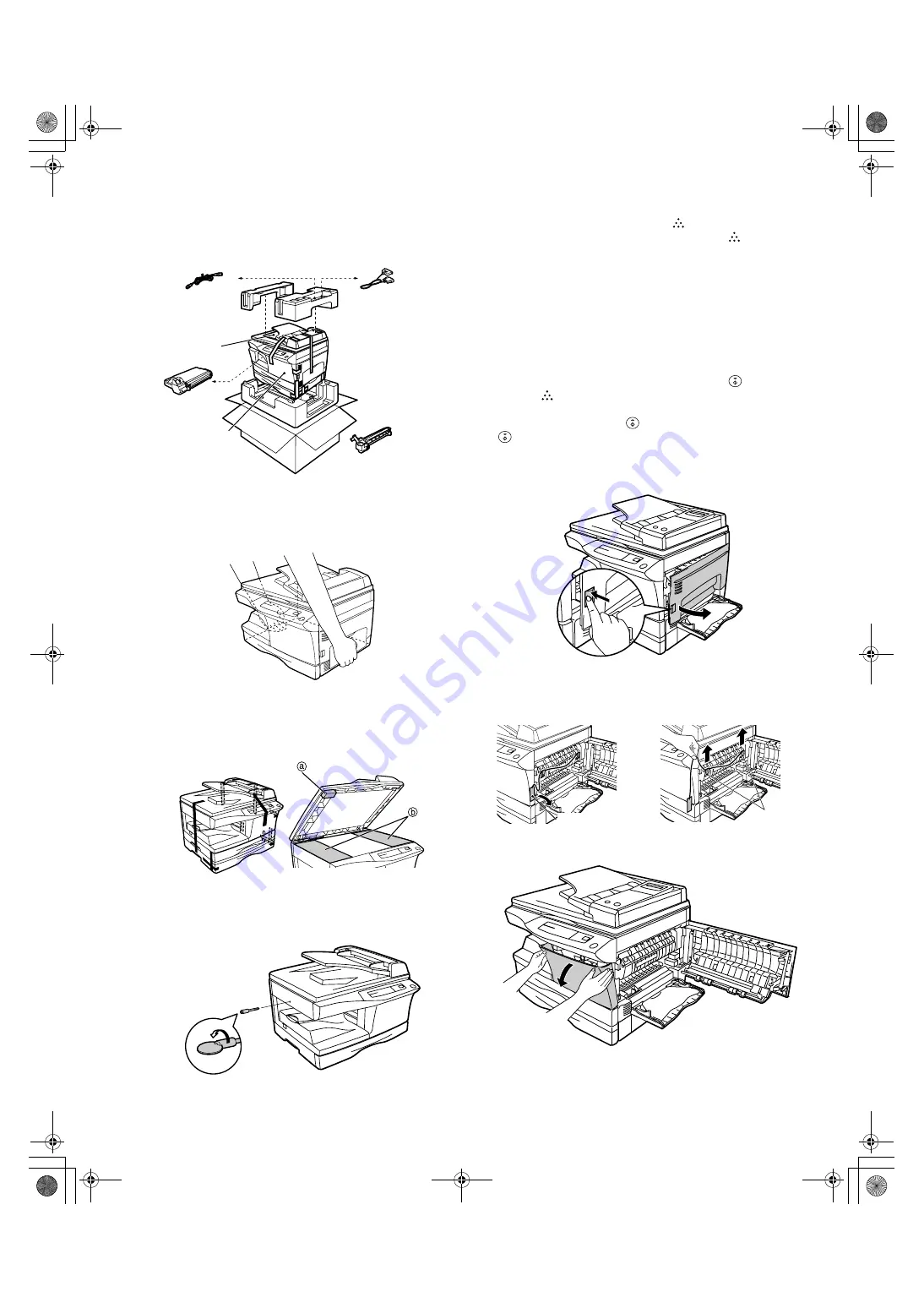
Open the carton and check if the following components and accessories
are included.
4. Unpacking
Be sure to hold the handles on both sides of the copier to unpack the
copier and carry it to the installation location.
5. Removing protective packing materials
1) Remove pieces of tape and protective cover. Then open the original
cover and remove protective materials (a) and (b).
2) Use a coin (or suitable object) to remove the screw.
Store the screw in the paper tray because it will be used if the copier
has to be moved.
6. Installing the TD cartridge
The TD cartridge replacement required (
) indicator will light up when
toner is needed. If copying is continued while the
indicator is lit,
copies will gradually become lighter until the copier stops and the
indicator begins blinking. Replace the old TD cartridge by following the
procedure given below.
Note:
•After the copier stops, it may be possible to make a few more copies by
taking the TD cartridge out of the copier, shaking it horizontally, then
reinstalling it. If copying is not possible after this operation, replace the
TD cartridge.
•During long copy run of a dark original, the ready (
) indicator may
blink, the
indicator may light up, and the copier may stop, even
though toner cartridge is not empty. The copier will feed toner up to 2
minutes and then the ready (
) indicator will light up. Press the print
(
) key to restart copying.
1) Ensure that the bypass tray is open and then open the side cover by
pressing the open button on the side cover.
2) Remove the CAUTION tape from the front cover and remove the two
protective pins from the fusing unit by pulling the strings upward one
at a time.
3) Push gently on both sides of the front cover to open the cover.
Copier
Power cord
TD cartridge
Drum cartridge
(installed in copier)
Operation manual
Printer driver (CD-ROM)
Interface cable
(IBM PC/AT or compatible computer)
CAUTION tape
Protective pins
+ ! #$! %&'()*
Summary of Contents for AL-1043
Page 115: ...AL 1551 CIRCUIT DIAGRAM 13 8 OPU ...
Page 116: ...AL 1551 CIRCUIT DIAGRAM 13 9 GDI PWB ...
Page 117: ...AL 1551 CIRCUIT DIAGRAM 13 10 GDI MEMORY PWB 6MB ...
Page 118: ...AL 1551 CIRCUIT DIAGRAM 13 11 POWER SUPPLY 120V 127V ...
Page 119: ...AL 1551 CIRCUIT DIAGRAM 13 12 POWER SUPPLY 200V Series ...


